I just thought you might like to see the specs of my OPT's. +/- 1db from 10 to 50,000 hz @ 30 watts, +/- 3db from 30 to 20,000 hz at 75 watts. PP 3500 ohms. Max current 175 ma per half of the primary. Primary winding imbalance less then 1/2%. Ultralinear taps at 43%. Secondary 8 ohms tapped at 4 ohms. A tertiary feedback winding center tapped.
R14/C6 is that part of a feedback circuit or just a bypassed cathode resistor? And I once read somewhere that if two cathodes are to share the same resistor you simply double the bias resistor value you derive from the load line? So R23 would become 19.15K? In wanting to stay as close as possible to the original schematic the neon bulb will become two. I think they are there to protect against peak voltage at startup? They may not be necessary with a CL resistor but they won't cause any harm either. The tuning caps and the plate chokes will stay. (I'm assuming my OPT's are no better than the originals.)
The major difference in the audio circuit will be at the input. V1a and V1b will become out of phase voltage amps driven by the input transformer. V3 and V4 are direct coupled, is there any reason V1 and V2 can't also be direct coupled? Then don't R24,R28, C19 and C20 become unnecessary?
If memory serves, the major cause of phase shift through a multistage amp is the coupling caps? If the first three stages are direct coupled won't that minimize phase shift? And lastly I would like EL34 to be cathode driven if only because that's the way Sol did it. But then I wonder what is the effect of applying feedback to the cathode of cathode driver? Or would I apply it to 6CG7 plates? Is there any reason I couldn't apply the feedback through C17 and C18? Of course the values would have to change but it keeps closer to the original circuit doesn't it? Thanks, Kevin
R14/C6 is a bypassed cathode resistor, the bottom of which connects to the OPT secondary through R8, R72 & R70 plus a trimmer capacitor. This is the main feedback path.
C17 & C18 are tiny capacitors. 1.5 micro-microfarads, or what we now call picofarads. (read the notes) They will affect only the very highest frequencies and are there to trim the square wave response. There's a couple other networks with small caps there for a similar purpose. I think uncle Saul was a good designer and paid a lot of attention to the small stuff that others did not. But most of this was for his OPT and his circuit layout, not yours.
If I understand correctly what you want to do is to convert the 9 into a full balanced differential design by way of an input transformer. Eliminate the no longer needed phase inverter stage (V3) making it into a diff. amp and convert V1 into a direct coupled diff amp as well. (there is no V2 in the schematic) That's a worthy project for an experienced person. Are you really up to that? If your input transformer has some gain you may not need that first stage. (V1a looks like it provides switchable absolute phase) Anyway I hope you haven't bitten off more then you can chew. But for me it's late. Time to go watch the sumo matches on NHK world TV.
Yes, these tiny capacitors are just for fine-trimming with their capacitance mainly being defined by the output transformer. You could also use a pair of enamelled wires per capacitor that you twist while observing the square wave response at the scope.
There's a capacitor of this purpose also in the famous McIntosh MC-3500/MI-350 amplifiers from 1969: C9 from the OT's cathode winding to one V11 grid (pin 7 of the first 6DJ8). It's nominal value is 1.5 pF, in other words: It needs to be adjusted accordingly.
Best regards!
There's a capacitor of this purpose also in the famous McIntosh MC-3500/MI-350 amplifiers from 1969: C9 from the OT's cathode winding to one V11 grid (pin 7 of the first 6DJ8). It's nominal value is 1.5 pF, in other words: It needs to be adjusted accordingly.
Best regards!

I built a mono differential amp for a man in the Hudson river valley using AD1 triodes. That was a pain. But he loves the amp. I built it with help from Kevin Kennedy, I owe him a lot on that one. I built Arthur Loesch's 6DJ8 preamp and I love it! My plan is to build this amp for use as the upper half of a bi-amped system for my Snells with a transistor amp for the low end. As much as I've stared at this schematic I never noticed there is no valve 2? That I can remember I've never seen Saul Marantz's name in print. Thanks for correcting me. I only heard it once when I spoke with Doc Hoyer. Doc pronounced it Ma-raantz and said he knew Saul. Called him a monkey at a typewriter which I thought was a bit harsh.
I thought the feedback circuit was to V1b which would make it global feedback? I know it's hard to read but I think that is resistor RB, which along with RA is used to adjust the damping factor. I think I'll have to double the feedback circuit coming off of the end taps of the feedback winding.
From my calculations, always suspect, valve 1b is running at 91 volts across the tube, standard for the 6DJ8. Valve 3 however is running at 300, hence the neon bulb. It must be somewhere around 2 ma I think.
The Sowter is a 1-1 ratio so no gain.
Yes HollowState, you have the general plan for the amp correct. I intend to change just what I have to to make it a differential amp. Then once it is up and running it will be easier to back out the tweaks if necessary.
I built the transformer pots from five inch square aluminum tube. Capping one end by welding on aluminum sheet. I received the potting epoxy Wednesday so this weekend I'm hoping to pot the transformers.
I think I have enough information to come up with a first draft of the schematic.
Right now I have to go put a new drive train in a Toyota Sienna van.

I spoke with Kevin at VAC and he gave me some more information about the amp. The original was prone to oscillation hence the 30% feedback. He said c17 and c18 are there for ultra high frequency feedback. He also verified what I suspected. The main feedback loop circuit is tailored to that circuit and will have to be redesigned from scratch in a differential amplifier. He also said the TC-6 plate chokes on v6 and v8 give them a different high frequency response than valves 5 &7. But that for my amps it would be worth trying plate chokes for all four EL34's.
My input circuit has a high pass filter with a 3db down point of about .7 hz. And the RC filter beyond the input transformer's 3db down point is just under 23K. My hope is that I've done the calculations correctly and that by curbing the really high frequencies the amps will be more stable and may need less feedback. That rolloff may need readjusting if the high end is too attenuated.
My input circuit has a high pass filter with a 3db down point of about .7 hz. And the RC filter beyond the input transformer's 3db down point is just under 23K. My hope is that I've done the calculations correctly and that by curbing the really high frequencies the amps will be more stable and may need less feedback. That rolloff may need readjusting if the high end is too attenuated.
After suggestions from more knowledgeable people than I, I have scrapped my input scheme. One of them helped me focus on my original conception for the amplifier. Outside of the initial phase reversal tube, V1a, and the first voltage amplifier, V1b, the amplifier is essentially a differential amplifier. Also, I do not agree that the 6CG7 driver stage would not provide a differential signal. Whatever AC signal gets past the 100k cathode resistor will be shunted to ground. And if not wouldn't get passed the opposite cathode resistor. Time will tell. I may have misnamed this thread and now want to call it Differential 9. It's not as if I were going to modify an original, rare Marantz amplifier. What I am building is a new amplifier based on a classic design. And I think that is a worthy project.
 Thread renamed by request of the OP.
Well, the NE2 bulbs on the 6CG7 should go from grid to cathode. Not grid to ground.
And just to knit pick, bias pot R52 is missing it's 5K catch resistor.
And just to knit pick, bias pot R52 is missing it's 5K catch resistor.
Last edited:
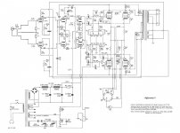
If anyone is still following this thread I need to make another change to the schematic. It was pointed out to me that the bias meter on the original is actually a volt meter. It is used to measure the drop across each of the 24 ohm cathode resistors. But the common resistor, R58, will always have 220 ma flowing through it to ground. So it seems R58 is an artifact of the meter they used and does serve any other purpose? I think I should connect my 0-100 ma ammeter directly to ground and use the 24 ohm cathode resistors as a check on the meter. With this change I should be able to delete R58 entirely?
mr2racer 58,
Forget about the effect on the meter, and consider the effect on the output tubes.
The total of 4 cathodes currents are 220 mA, so if you replace R58 3.3 Ohms with a jumper (short) . . .
Then the self bias voltages will be reduced by 0.72 Volts.
That 3.3 Ohm resistor, because it is common to all 4 cathodes, looks like a 3.3 x 4 = 13.2 Ohm resistor to each of the 4 output tubes.
24 + 13.2 = 37.2 Ohms . . . Now
24 + 0 = 24 Ohms . . . if you short across R58 (jumper)
An output tube with a transconductance of 10,000 uMhos, is 10 mA / Volt of bias.
0.72 Volts x 10mA/V = 7.2mA more current in each tube.
Actually, because the tubes are self biased, the will be a little bit correction, perhaps each tube will have 5mA more current (20mA total extra current)
Just my $0.02 worth.
Have fun building, modifying, and listening?
Thanks I had understood that all the current was going through R58. I have also learned that ammeters can introduce resistance into the circuit. SoI'm scraping the ammeter in favor of a pair of small jacks where I can plug in a DVOM. I've made the changes on the schematic.
Attachments

Circling back to the neon bulb. There's a nifty device called a Diac. I've started using 30V versions in these situations.
- Home
- Amplifiers
- Tubes / Valves
- Differential 9 Power Amplifier