Hey, hopefully a quick fix for this issue here.
A T0-3 transistor based PA amp I was using with my custom sub just blew up. Was only using one channel...
I beep-tested all the TO-3s, 16 in all and 3 appear to no longer conduct.
Does this indicate that they are busted? That channel hums quite bad now.
They are the furthest from the aftermarket 12cm PC fan I installed. It's probable that the thermal protect was cooler than they were and was ignored. I guess I need to work on the fans position.
The fuse did go too, as did another in another amp in the system when it happened. There was fireworks.
Hopefully as easy as just replacing the non-conducting TO-3s, right? (I hope)
They are already 4quid each...
Thanks in advance
How to test transistors: http://www.diyaudio.com/forums/solid-state/18151-testing-transistors-dmm-vom.html
You should test the driver transistors as well, they might have blown as well.
And you probably will need to replace all the output transistors from one channel, with matched ones. See Matching Power and Driver Transistors.
You should test the driver transistors as well, they might have blown as well.
And you probably will need to replace all the output transistors from one channel, with matched ones. See Matching Power and Driver Transistors.
Thanks Erik
I will look those over. I used the diode test, I still find it odd that only 3 transistors read OPEN and the rest beep (closed), I was in hope that this would be sufficient diagnosis for these 2-pin transistors.
I will look those over. I used the diode test, I still find it odd that only 3 transistors read OPEN and the rest beep (closed), I was in hope that this would be sufficient diagnosis for these 2-pin transistors.
You need to check both pn junctions in both directions to ensure they are rectifying.
Also check CE is open circuit.
I had a nasty one once where a transistor checked ok using DMM.
I checked it again using a transistor HFE meter and it read 1.
It should have read at least 40.
Also check CE is open circuit.
I had a nasty one once where a transistor checked ok using DMM.
I checked it again using a transistor HFE meter and it read 1.
It should have read at least 40.
The beeping ones, what is the voltage drop? Around 600 mV? If less, they are all blown. The open ones might still be alive.
Whoa, 6 combinations across 8 transistors, 48 tests per channel with no guarantee that the new ones ordered will match??? Sod that.
Another idea...
The drawing in the service manual contradicts the parts list, the BJT currently installed which are MJ15022/23. The drawing shows 2SB554, 2SD424 which are obtainable on ebay $18.96 free postage, for 5 pairs. Are these interchangeable?
Four pairs (one channel) of MJ would cost £30 ($40), perhaps worthwhile replacing both channels and sell any working Motorola's, if they're interchangeable? It seems there both TO-3.
I may still tab up the current situation for **** n giggles anyway.
Here's the template I will be using. I'm going for it, 96 tests. Let's do it!
Beware buying semiconductors from ebay. Way to many fakes around.
If all these outputs are effectively in parallel then look at testing the amp with just a single pair fitted. Once the amp is proved good then you can add the other pairs.
99.9% of failures in TO3 power devices manifest as them reading short circuit from C to E.
If all these outputs are effectively in parallel then look at testing the amp with just a single pair fitted. Once the amp is proved good then you can add the other pairs.
99.9% of failures in TO3 power devices manifest as them reading short circuit from C to E.
2sd424 is the most faked transistor in the universe. Obsolete since the 70s. Literally 100% of any part you will ever buy will be fake, and blow up instantly. Don't even attempt to buy these.
Haha!! avoid those then.
Thanks mooly,
Observing correct polarity of leads, joining C to E of the transistors give the DMM reading of;
472 for the 4 NPNs and 482 for the PNPs in working channel.
The other channel however, 4NPNs gives a beep, 3 PNPs read 643 but the other gives a beep.
I might add that the batches differ between the channels, all were made in year 95 but the weeks vary.
I'll watch out for fakes, obviously I'm trying to minimize cost but it looks like I probably will need 4 new pairs right?
Beep is not good enough a test.
I found surviving non-blown MJ15024/25 that reads .45 v or below (most were .43 or .44) CB would blow up 1 minute after getting hit with 170 VDC (DC caused by the driver board that was also blown by current leaking out the base lead of the OutputTransistor's).
I ended up replacing all 20 OT and using the one that was .47 v CB as a driver transistor.
Most of my emitter resistors were blown too. Check them. If your emitter resistors are not .5 ohm, you probably need to match the new output transistors Vce. I use gain 10 (100 ohm base resistor, 10 ohm load resistor) with clip leads to match Vce. Which means you need extra OT's to put a couple or 6 outliers in the spare parts bin. I only had two .11 v Vce versus the rest at .13 or .14 Vce of the 24 On semi parts I bought.
I'd buy OTs in the UK from Farnell or RS, unless Andrew wants to recommend a very specific E-bay vendor that is not a crook. there is one honest e-bay vendor in the USA I read, specializing in lateral FETs, which these aren't. I like what transistors I get from ON semi, fairchild, and ST via Farnell (US) .
See this about finishing the job: vintage amplifier repair/upgrade manual - diyAudio
I had stuff blown all the way back in the driver, 116 parts in all. I'm in the midst of a major overhaul of the protection circuits of my $600 (OEM) PA amp, since there are $600 1500 W PA amps (dodgy protection) and $1000 PA amps (serious protection) talking about ones with real watts of course. There are **** PA amps costing even less where the watt reading is good for 10 seconds, it seems. Repairmen on here seem to respect Crown, QSC, Peavey, Yamaha, PA amps.
Last edited:
The beep test is good and quick - because any transistor that beeps in any way is blown. No need to do a full test if any portion of the test shows as shorted.
My DVM diode test beeps anything 8.2 ohms or lower. Not much of a quality check on a transistor. Your instrument may vary.
You are testing all these out of circuit ?
'Beep' tests are very meter specific. Out of circuit and there should be no continuity from C to E when correctly polarised test leads are used. In other words red lead on the collector, black on the emitter, vice versa for PNP. Use both high and low ohms ranges to check.
(Analogue meters may have reversed polarity to DVM's)
Alright,
I tested these in-circuit, unfortunately as soldering iron currently out of order.
@Welcome, you could be right,
The main indicator here as per moolys instructions, probes across CE (observing correct polarity); the top row of NPNs gave readings, whilst the lower row also NPS in the exact same test arrangement all gave beeps. After reversing probes, 3 of matching PNPs gave same result, except for just one which I think is ok but now orphaned. What should I call him/her?
SO 7 of the 8 in 'channel A' are melted, melted because when the amp popped, the heatsink was roasting. That channels fuse blew, as did another fuse in another amp in the system (active 3-way).
There was sparks, the fuse and to-3s are intact so something has chunks missing. Must find it.
Yet to check the drivers, which I presume is another name for supply regulators?
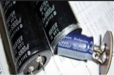
Another visual observation; with a new fuse in that channel to conduct it again, fuse stays ok but one the power caps starts cooking away (bubbling and pops, basically this one is ruined). Switched off to prevent any more pain. Poor Cap.
May aswell replace power caps... 100v 2200uf rubycons on ebay for not much from Poland, set's of 4.
Before buying anything and soldering iron permitting I will try one pair of TO-3 as suggested!! £30 quid though damnit!
I tested these in-circuit, unfortunately as soldering iron currently out of order.
@Welcome, you could be right,
The main indicator here as per moolys instructions, probes across CE (observing correct polarity); the top row of NPNs gave readings, whilst the lower row also NPS in the exact same test arrangement all gave beeps. After reversing probes, 3 of matching PNPs gave same result, except for just one which I think is ok but now orphaned. What should I call him/her?
SO 7 of the 8 in 'channel A' are melted, melted because when the amp popped, the heatsink was roasting. That channels fuse blew, as did another fuse in another amp in the system (active 3-way).
There was sparks, the fuse and to-3s are intact so something has chunks missing. Must find it.
Yet to check the drivers, which I presume is another name for supply regulators?
Another visual observation; with a new fuse in that channel to conduct it again, fuse stays ok but one the power caps starts cooking away (bubbling and pops, basically this one is ruined). Switched off to prevent any more pain. Poor Cap.
May aswell replace power caps... 100v 2200uf rubycons on ebay for not much from Poland, set's of 4.
Before buying anything and soldering iron permitting I will try one pair of TO-3 as suggested!! £30 quid though damnit!
If a reservoir cap is bubbling then that is way to much of a coincidence. Could you have a power supply fault such as a shorted diode in the bridge ?
You need to power this thing up with a bulb tester which will stop parts frying and fuses blowing.
And there are a lot of fake caps around too...
You need to power this thing up with a bulb tester which will stop parts frying and fuses blowing.
And there are a lot of fake caps around too...
Attachments
By power supply fault, you mean drivers (regulators>same thing?)
I probed each of the cases when testing individual emitters.
I also learned something new from wiki which helped me remember;
NPN; not pointing in
PNP; pointing in proudly. Useful.
I probed each of the cases when testing individual emitters.
I also learned something new from wiki which helped me remember;
NPN; not pointing in
PNP; pointing in proudly. Useful.
Last edited:
Rubycon is the most faked capacitor brand in the universe. Literally 100% of any part you will ever buy on Ebay will be fake, and blow up instantly. Don't even attempt to buy these.
haha!!
Okay, the service manual states in case of excessive hum on channel with no signal present:
- Hum null trim pot open or burned
- Mismatched capacitance value of output filter capacitors.
That's all.
Will check now
So theres something. No idea what to make of it, theres hum and one cap bubbles away with current applied.
Appreciate your guidance, especially fake-watch advice.
Okay, those hum null resistor pots seem to not-conduct after I apply the doide test function across the terminals, but if quickly switch them around they do conduct, like it some certain resistance threshold something?
Anyway, I found a defective driver transistor in the dodgy channel - from C to E a certain polarity it conducts, the one in other channel which is identical doesn't do this. The driver transistor is also wobbly in it's seat!
So what can we conclude? Perhaps the heat seeped to this driver and unseated it?
I'll replace what I can and report back!
Last edited:
- Status
- Not open for further replies.
- Home
- Amplifiers
- Solid State
- diagnosing faulty transistors