My son and I are about to start on our first of what we hope to be a number of building projects. A transformer DI box. We have chosen the more complete of those shown on the Jensen website:
http://www.jensentransformers.com/as/as066.pdf
My questions are about the wiring. It is simple enough that I was considering just direct wiring the electrical components between the switches, sockets and transformers. If we do that, how do we run the grounding connections?
1) Can we just wire them to different spots on the bottom of the aluminum enclosure and utilize the enclosure floor to provide the grounding circuit?
2) Or should we collect all the ground in one spot (star grounding?)? If so, should that spot be at the input jack? The 1/4" jacks recommended by Jensen connect the collar to the enclosure, so the collar must be connected to the box. Is that a problem?
Alternatively, we could mount the resistors on a small prototyping PCB and run wires to the jacks and switches.
3) Is there any issue with picking up noise if we run relatively long runs (3 - 4 inches) of wires inside of the enclosure? The wires wouldn't be twisted pairs (I don't think).
4) The small prototyping PCBs I see have a rectangular array of small holes, with each hole having its own isolated copper soldering pad. How do we connect the different components together, and connect wires to them? I tried putting 2 leads through a single hole, and the hole was too small. Do we just put the leads through adjacent holes, and then twist the leads together to connect them. Then solder both the device into the board and the point where the leads/wires are twisted together?
Thanks in advance for your help.
Hi:
In building a di-box, there are a few things to be kept in mind, namely:
-the box should be made of metal, preferably iron, so as to shield the EMI-sensitive components;
-the legs of the box should be made of material with good insulating properties;
-the box should be compact and small so as to make the internal wires as short in length as possible;
-the connectors and switches should be placed logically, which also helps to keep the length of the internal wires short and allows us to avoid using special PCBs for mounting components.
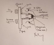
After the connectors and the switches are installed into the box, the resistors and wires should be connected directly to their soldering joints (no additional PCB needed). The star ground point is the ground of the input connector, which is also connected to the box. In my opinion, it would be best to mount the input connectors and attenuator and filter switches on the top side of the box whereas the output connectors and the output ground lift switch should be mounted onto the rear side.
I hope this is of some help to you.
Regards,
Milan
In building a di-box, there are a few things to be kept in mind, namely:
-the box should be made of metal, preferably iron, so as to shield the EMI-sensitive components;
-the legs of the box should be made of material with good insulating properties;
-the box should be compact and small so as to make the internal wires as short in length as possible;
-the connectors and switches should be placed logically, which also helps to keep the length of the internal wires short and allows us to avoid using special PCBs for mounting components.
After the connectors and the switches are installed into the box, the resistors and wires should be connected directly to their soldering joints (no additional PCB needed). The star ground point is the ground of the input connector, which is also connected to the box. In my opinion, it would be best to mount the input connectors and attenuator and filter switches on the top side of the box whereas the output connectors and the output ground lift switch should be mounted onto the rear side.
I hope this is of some help to you.
Regards,
Milan
Thanks
Thanks for the reply. We've already got an aluminum box that's a little larger than I think we need but not too much. I know you said steel is preferred. How much worse is aluminum?
Regarding the PCB, two of the capacitors that we purchased are PCB mount (I didn't pay close enough attention). We could replace them, but thought that it would give us a chance to get some PCB soldering experience if we used them on a small PCB board. We'd also probably use it to mount the resistor and capacitor for RFI suppression. It looks like the leads to C2 and C3 could be twisted pairs as we've laid out the components. Is this such a bad idea that we should buy new capacitors and stay totally direct wired? If its ok to try the PCB, any advice on how to make connections on this type of prototyping board were the soldering pads are not connected?
Last question is about star grounding. There are about 6 separate ground wires that need to be attached to the grounding point. I don't think that I can fit all of them into the grounding lug on the input jack. Can I use the grounding lug on the other 1/4" jack (output to a guitar amp)? That jack is a 2nd ground point anyway.
Thanks again for all of your help.
I've found some of our answers
Found that what I've been calling a PCB is really perfboard and with that was able to find lots of instructions on how to work with it. But won't have to because we decided to replace the PCB capacitors with leaded ones so we can direct wire the whole project. We are staying with the aluminum box. If it has problems, we will swap into a steel box later on.
Only real issue is the grounding question. Since we can't think of a way to ground everything at the same point, we're going to stay with using the ground lugs from both of the 1/4" jacks.
If anyone can comment on the last point, I'd appreciate it, but will proceed as described otherwise. Thanks again to everyone who have viewed this thread and especially to moamps.
Re: I've found some of our answers
Don't do it that way, you'll create a ground loop. You should isolate the ground lug of one of your 1/4" jacks. There are many ways to do this. Can you find a plastic 1/4" jack? A plastic box (IMHO this will work fine)? Are you handy enough to rig up a plastic washer and sleeve to isolate the metal jack?
bkspero said:Only real issue is the grounding question. Since we can't think of a way to ground everything at the same point, we're going to stay with using the ground lugs from both of the 1/4" jacks.
If anyone can comment on the last point, I'd appreciate it, but will proceed as described otherwise. Thanks again to everyone who have viewed this thread and especially to moamps.
Don't do it that way, you'll create a ground loop. You should isolate the ground lug of one of your 1/4" jacks. There are many ways to do this. Can you find a plastic 1/4" jack? A plastic box (IMHO this will work fine)? Are you handy enough to rig up a plastic washer and sleeve to isolate the metal jack?
Grounding
I'm sure that I could isolate the ground of one of the jacks that I have, or buy a plastic bodied jack as a replacement. But why would Jensen recommend using these (I bought the exact brand and model that Jensen recommended) in a metal box if they felt that 2 grounding locations were a problem?
Am I missing something about a 2nd ground from that?
I should have looked at the schematic before replying 
You will be able to avoid a ground loop provided that you use the ground lug on the output 1/4" as the tie point for all the other grounds.
You will be able to avoid a ground loop provided that you use the ground lug on the output 1/4" as the tie point for all the other grounds.
Re: I've found some of our answers
Hi:
You should mount the jacks as close to one another as possible and then solder a thick piece of uninsulated (bare) wire between the ground lugs to connect them. You will then be able to use the length of the wire as a larger star-ground point (NB: the jacks need not be isolated from the chassis).
Regards,
Milan
bkspero said:Only real issue is the grounding question. Since we can't think of a way to ground everything at the same point, we're going to stay with using the ground lugs from both of the 1/4" jacks.
Hi:
You should mount the jacks as close to one another as possible and then solder a thick piece of uninsulated (bare) wire between the ground lugs to connect them. You will then be able to use the length of the wire as a larger star-ground point (NB: the jacks need not be isolated from the chassis).
Regards,
Milan
How thick a wire?
How thick should we make the wire? We are planning to use 22 ga. solid wire for other purposes in the box. That's much heavier than the leads from the Cinemag CM-DBX transformer. Is it heavy enough? I guess I also have 12 ga solid conductor ground wire from Romex cable. I'm not sure that we can get that into the hole in the ground lug, though. Is that what we should be shooting for?
How thick should we make the wire? We are planning to use 22 ga. solid wire for other purposes in the box. That's much heavier than the leads from the Cinemag CM-DBX transformer. Is it heavy enough? I guess I also have 12 ga solid conductor ground wire from Romex cable. I'm not sure that we can get that into the hole in the ground lug, though. Is that what we should be shooting for?
- Status
- Not open for further replies.
- Home
- Live Sound
- Instruments and Amps
- DI Box wiring questions