I'd say connect Blue to Green, but you can easily check.
You put primary and secondary in series, so you should have some 750 ohm of DCR.
When connected wrong you have primary and secondary parallelled and DCR is some 190 ohm.
By connecting primary and secondary in series you have twice the number of windings; that will give 4 times the inductance.
You put primary and secondary in series, so you should have some 750 ohm of DCR.
When connected wrong you have primary and secondary parallelled and DCR is some 190 ohm.
By connecting primary and secondary in series you have twice the number of windings; that will give 4 times the inductance.
Will the 126C still pass 15mA as it was designed to do?
I tried connecting another interstage I have with primary and secondary in series. Both are 333 ohms. In series connected either way they total 666 ohms. What am I not understanding here?
I tried connecting another interstage I have with primary and secondary in series. Both are 333 ohms. In series connected either way they total 666 ohms. What am I not understanding here?
Magnequest EXO-010 is 225H at 15mA and not particularly expensive with a more reasonable form factor than the Hammond and very likely improved performance.
The current capability will not change.
When you connect wrong you also measure some 180 ohms in case of 126C.
But what counts is that you have the primary and secondary in series with respect to phase.
When not the inductance cancels to zero.
But Andy, experienced DIY'er as you are, I expect you to have the most basic of measurement gear, like an LCR meter.
Do you mean a multimeter, which I have, or one specifically for inductance? Most LCR meters I see have a max. inductance of 20H. What do you recommend?
OK - so I'll try this with the 126C and see. Should be interesting.
OK - so I'll try this with the 126C and see. Should be interesting.
Last edited:
I mean an inductance meter, mostly combined with the option to measure capacitance and resistance as well.
Good ones with good range and different measuring frequencies are expensive however.
Just try; when connected incorrect you immediately find out as the valve is unloaded.
Good ones with good range and different measuring frequencies are expensive however.
Just try; when connected incorrect you immediately find out as the valve is unloaded.
As interstage transformers are designed to carry DC current only for the primary (the secondary is usually DC free), the current capability will be halve the original design value. If windings are connected in series, DC flows through twice the number of windings on the same core. Magnetic flux is determined by the current times number of windings (flux will double, but inductance will be 4 times higher). If you connect the windings in series in antiphase, the flux generated by one winding will be cancelled by the other one - hence zero induction as already mentioned before.
If you have no LCR meter available, you may simply try out. The operating point of the valve will not change as DC resistance is the same independent of the phase of the series wiring. In one case, you will get full output signal - if connected in antiphase, you will get no output signal. As inductance never cancels out completely, measure at low frequency to minimize influence of stray inductance (which will not cancel)
If you have no LCR meter available, you may simply try out. The operating point of the valve will not change as DC resistance is the same independent of the phase of the series wiring. In one case, you will get full output signal - if connected in antiphase, you will get no output signal. As inductance never cancels out completely, measure at low frequency to minimize influence of stray inductance (which will not cancel)
Taking a new look at this older thread, I can see a circuit which seems perfectly viable. It would use SIC diode bias maybe with a resistor thrown in for a bit of feedback. Have a look at this and give me some comments. I was looking at a plate choke design that would feed a solid state amp, and this might do it.
Attachments

Interesting! Why do you use 20 Schottky rectifiers in series rather than LEDs or ordinary silicon diodes or a zener or even a bigger resistor?
Interesting! Why do you use 20 Schottky rectifiers in series rather than LEDs or ordinary silicon diodes or a zener or even a bigger resistor?
On the basis of using them in my 26 preamp and hearing them in Ale Moglia's 01A preamp, they sound better. Nothing more elaborate than that. I'm using a string of 10. I don't know the sonic effects of doubling that to 20. They aren't exactly cheap, but worth what they cost.
My mistake. The circuit you posted has "x 20" on it. I assumed that this was per tube. How much voltage drop are you getting per Schottky?
My mistake. The circuit you posted has "x 20" on it. I assumed that this was per tube. How much voltage drop are you getting per Schottky?
10 give me 8.6v, so 0.86v
Have a look at this and give me some comments.
I'd question the use of 2A3 in lieu of other DH tubes which have less input capacities and require less power to heat the filament. Output impedance of 1k (with your resistor bias) or 2k (for example) will make no difference when driving >47k load (or 20k).
71A is a standout for lower input capacities (plural), similar mu and bias, somewhat lower B+ and 1/10th the filament current. Most who have compared 71A and 2A3, power output aside, have found 71A to be the better tube (google).
HK
Last edited:
I'd question the use of 2A3 in lieu of other DH tubes which have less input capacities and require less power to heat the filament. Output impedance of 1k (with your resistor bias) or 2k (for example) will make no difference when driving >47k load (or 20k).
71A is a standout for lower input capacities (plural), similar mu and bias, somewhat lower B+ and 1/10th the filament current. Most who have compared 71A and 2A3, power output aside, have found 71A to be the better tube (google).
HK
Hmm - I sold all my 71A except one pair. It is an idea. I have plenty of 4P1L and I intend to try that with SIC diode bias. 2a3 was just a theoretical idea really. Thanks for the post.
Hmm - I sold all my 71A except one pair. It is an idea. I have plenty of 4P1L and I intend to try that with SIC diode bias. 2a3 was just a theoretical idea really. Thanks for the post.
One pair could well be all that you need.
160H is about right for Type 26, 2k Rp types require less.
Capacitance comes with that 1k2 winding. If they are gapped right and you still want to try them, use 5k resistor between plate and the choke to decouple this C.
160H is a mismatch for <2k Rp types, if you decided to go with the 2A3 or 71A etc, with the low voltages I would suggest a 1:1 bifilar wound transformer, primary inductance to suit your preference. Otherwise use a choke but be aware of the interaction with any inductive loads; that 0.2uF quickly becomes 2uF, not nearly as appealing and still with issues to do with LF peaking and resonance (ask me how I know).
HK
Last edited:
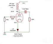
I now have a 6C4C preamp up and running, and listening to it now. Schematic attached. It uses Rod Coleman regs for the filaments. I built this in order to have a preamp stage with a low output impedance, that could drive an average solid state amp if needed.
My usual preamp is a 26 with the same NP Acoustic large plate chokes, so that's my immediate comparison. I right away missed the spark and vividness of the 26 and the lush midrange on vocals. What we have here is a very solid sound which drives my 4P1L PSE output stage well. The presentation is clean with no obvious strain or overload. Sound quality is very neutral, though the balance is a little more towards the bass with less atmosphere and life and fine detail in the higher treble. The predominant quality is smoothness and lack of strain. Bass is well defined.
I'll leave it in my system for a day or two to see how I feel with extended listening. It's a perfectly valid preamp tube if low output impedance is required.
Attachments
Last edited:
A 0.2uF cap isn't going to be enough to drive much of anything, hopefully you're just off by a decimal point.
The PTC of resistance associated with Schottky diodes would make me question that choice for biasing. How about a 16 ohm/50W resistor?
The PTC of resistance associated with Schottky diodes would make me question that choice for biasing. How about a 16 ohm/50W resistor?
I'll look at the output cap at some point, but the sound is there with 0.2uF. I want to use teflon here, and the Russian teflon caps I use start to get big when you parallel them up. I don't want to compromise on the quality of the output cap.
This isn't filament bias - it's SIC diode bias. If the SICs were replaced with a resistor for 25mA and 16.6v that would be a 664R resistor. I never use cathode bypass caps because I've always found they compromised the sound quality, so that's not a choice I'd make. It could indeed be done in filament bias which is what you are suggesting. When I switched my 26 preamp from filament bias to SIC diode bias I preferred the sound with the SICs. So that was my starting point here.
This isn't filament bias - it's SIC diode bias. If the SICs were replaced with a resistor for 25mA and 16.6v that would be a 664R resistor. I never use cathode bypass caps because I've always found they compromised the sound quality, so that's not a choice I'd make. It could indeed be done in filament bias which is what you are suggesting. When I switched my 26 preamp from filament bias to SIC diode bias I preferred the sound with the SICs. So that was my starting point here.
Ah, the way you have it drawn and your previous projects suggested filament bias.
You are compromising enormously with the 0.2uF, and this is especially true if you plan to use this with a solid state amplifier.
You are compromising enormously with the 0.2uF, and this is especially true if you plan to use this with a solid state amplifier.
Yes - I used filament bias for years, but this year I'm using SIC diode bias. I could use filament bias with the SICs but I haven't tried that.
I have plenty of 0.1uF FT-2 teflon caps which I can parallel up if needed. I'll probably go back to my 26 preamp so I'm not throwing the heavy artillery into this preamp just now. I just have to drive my 4P1L PSE output stage and the 26 SIC bias sounds good doing that. I also tried a 4P1L preamp with the same NP plate choke/SIC bias and preferred the 26 in my system. These are all possible choices, though.
I'm quite liking the smoothness of the 6C4C for extended listening. Growing on me a little.
- Home
- Amplifiers
- Tubes / Valves
- DHT preamp, 2A3 preamp