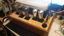

A new build of a 6C4C preamp. I like this a lot - dynamic, detailed, like listening to master tapes in a studio. It's far from an ideal build - solid state PSU with SIC 1200V diodes, lower current through the 6C4C. Just a basic build with parts I had available. But the outboard filament supply is quite a monster - huge chokes in choke input and then Rod's regs in the main chassis. I think it's worth optimising this preamp. The Svetlana 6C4C is a good sounding valve.

Thanks Rod. Please keep the suggestions coming - I want to improve this circuit as much as possible. It has promise.
Hi Andy,
Is 6C4C a Russian equivalent of 6A3 US? I tried to find 6C4C at TDSL with no luck. Do you have (or a link to) a data sheet?
Nice to see you're getting into previously uncharted waters.
Best, Robert
Is 6C4C a Russian equivalent of 6A3 US? I tried to find 6C4C at TDSL with no luck. Do you have (or a link to) a data sheet?
Nice to see you're getting into previously uncharted waters.
Best, Robert
Try to search 6S4S (the english "equivalent" of russian "C" is "S").
https://frank.pocnet.net/sheets/113/6/6S4S.pdf
https://frank.pocnet.net/sheets/113/6/6S4S.pdf
Octal base and more. You can safely run the 6C4C at 350V anode voltage likely due to better/sturdier construction. Plate dissipation at 15W is conservative. Can run without troubles at 16-17W too. IMHO, they are better than original 2A3's, 6A3's and 6B4G's....I have them ALL.With a little more searching 6C4C appears to be an octal base, so equivalent to 6B4G.
There is also the 2C4C, with 2.5V filament, but it's very rare.
I'm building a 6C4C stage in filament bias. Sounds better than a cathode bypass cap. In fact it sounds great. 6C4C is Svetlana quality.
Soory but these settings are totaly wrong. Dont want to be offansive, sorry, bur almost every passive complonnent value is wrong 🙁A new build of a 6C4C preamp. I like this a lot - dynamic, detailed, like listening to master tapes in a studio. It's far from an ideal build - solid state PSU with SIC 1200V diodes, lower current through the 6C4C. Just a basic build with parts I had available. But the outboard filament supply is quite a monster - huge chokes in choke input and then Rod's regs in the main chassis. I think it's worth optimising this preamp. The Svetlana 6C4C is a good sounding valve.
View attachment 1069895
1. Anode voltage of only 100V is simply too low - tube is voltage dvice not current device. should be more than 200v. Current can be smaller, even the half or more compared to the same tube in amplifier circuit...
2. Anode Rload is too high value of 10K. For the premplifier, when this tube of tube is employed, totaly opposite way is right.
smaller Rload values. Maybe smaller than 3K, should be checked. Distortion will be the minimal or same as with 10K BUT sound will be much better...
3. Grid stopper of 390ohms are doing almost nthing - should be inreased with respect to dynamic capacitance of tube.
4. 100K input grid termination is relatively OK but could be a bigger value u to 390K to accept tube stage before wityhot shunting tha output with 100K...
5. C output is too low value. Imagine next stage Rin of 47K or even 10K standard solid state... Should be 10uF in any way.
6. Output terminatination resistor of 470K is actually NOT the real termination res. Because one Rin from next stage IS. And should be from higher value 2.2meg to 4.7meg. Just to keep the output tied to gnd when preamp is not connected...
7. Kathode bypass capacitor is too low for this value of Rk. In any case shoud be checked with simulations, NOT with the simple RC time formula, because it is not valid in these context. What is the factor is the last C in PS colsest to the Anode, Rload. And offcourse output RC constant.
cheers
And dont get me wrong please 🙁
I don't accept half of your reasoning, though you have one or two points. In any case I would build this now in filament bias which sounds better.Soory but these settings are totaly wrong. Dont want to be offansive, sorry, bur almost every passive complonnent value is wrong 🙁
- I would use a resistor load because the tonal qualities are better than active loads on acoustic instruments. A plate choke is a possible alternative, but I like the sound of resistor loads.
- B+ would be around 300V because that's what I have available. Anode resistor would be scaled appropriately, could be 3K or whatever
- Grid resistor would be 100K, not bigger
- Output cap would be as low as possible allowing for decent bass response. Probably 1uF or less. If this were to feed a tube stage it would be much less than 1uF and made up of paralleled Russian teflon caps like FT-2, K72. The quality of the cap comes first here and may indicate a compromise on deep bass response.
- 390R is probably a bit high for a grid stopper - could be 220R
- Output termination resistor of 1 meg would be fine, or 2.2 meg as you say. If this stage were used to drive e.g. a 2a3 output stage directly then it would indeed be 470K.
- If a cathode bypass were used 40uF would be fine because it could be a DC Link not an electrolytic. Components that sound better are first choice for me because it's the tonality of the sound that matters. But anyway, filament bias sounds better so that's what it would be.
I've built 10Y and 46 stages in filament bias with resistor loads and they sound excellent. 6C4C is good even with a cathode bypass and will be better in filament bias, as the 10Y and 46 have been. I can see we have different priorities.
I thought grid stoppers were for the purpose of suppressing high frequency circuit resonances for the likes of rf/frame grid tubes designed for rf service but adapted for audio frequency use. Why need a grid stopper on a 2A3 or 6C4C?
- 390R is probably a bit high for a grid stopper - could be 220
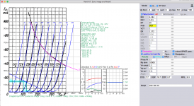
it is not issue of using R as Anode load it is OK BUT the value of that R is too high with respect to tube characteristics aind parameters... And that loos of DC voltage at the Rload are huge and unnecessary "eating" the same voltage from tube anode voltage... I will post the graph.I would use a resistor load because the tonal qualities are better than active loads on acoustic instruments. A plate choke is a possible alternative, but I like the sound of resistor loads.
B+ is power supply NOT Anode voltage. Anode Voltage is Va-Vk in this case circa 100V which is very lowB+ would be around 300V because that's what I have available. Anode resistor would be scaled appropriately, could be 3K or whatever
This is NOT grid resistor but Input resistor. This resistor is also the terminating resistor for the stage that comes before preampGrid resistor would be 100K, not bigger
The grid resistor is more grid stopper R...
opposite... It is NOT "probably" the value should be calculated with respect to Rin nezt stage and termination R at the output. C forming the time constant with parralel values of Rin next stage and Term R.Output cap would be as low as possible allowing for decent bass response. Probably 1uF or less. If this were to feed a tube stage it would be much less than 1uF and made up of paralleled Russian teflon caps like FT-2, K72. The quality of the cap comes first here and may indicate a compromise on deep bass response.
Rin next stage is something that could vary. For solid state amplifiers it is from 10K, 47K to 100K.
For tube amps Rin is higher in range of hudrede K.
For the example Your termination resistor is 470K assume that input resistor of the next stage is also 470K.
You have parallel load of 235K. C for -0.25db@20Hz is -3dd@1.6Hz = 1 / (2 x PI x 1.6Hz x 235000) = 0.42uF (0.47uF)
BUT for 47K Rin next stage total R is 470K II 47K = 42720ohm and C= 1 / (2 x PI x 1.6Hz x 42720) = 2.32uF
...
Opposite again. That is also time constant RC where R is Rgrid stopper and C is Dynamic capacitance. Cdyn = Cgk + [abs(-A) x Cga], where -A is gain of the stage. - sign is for phase shift of 180deg... That means that sygnal at the output will be phase inverted. 🙁390R is probably a bit high for a grid stopper - could be 220R
You can choose F cuttoff frequencu in HF region where Rgrid stopper should be working.
Rgs= 1 / (2 x PI x Fhf x Cdyn)
This Rgs also affects Sleeve rate, and should take a care not to use too "early" RC filter...
I cant find the electrode capacitance's for this tube but maybe take from 6B4G or 2A3...
again it is NOT termination resistor it is ONLY a part of Termination reistor. Real Value depending on Rin next stage... This resistor is only to prevent floating when the outout is not connected...Output termination resistor of 1 meg would be fine, or 2.2 meg as you say. If this stage were used to drive e.g. a 2a3 output stage directly then it would indeed be 470K.
That part is bit tricku because the classic RC formula dont wotking there. It should be calculated for the start for total reactive impedance not to change more than 10% at LF. So the ractive first is to calc impedance of reactive real part of Cbypass than put it in parallel with R, form the equationo for 1.1 times more value. You will get square equation at the end and solve for one result thatis not complex.If a cathode bypass were used 40uF would be fine because it could be a DC Link not an electrolytic. Components that sound better are first choice for me because it's the tonality of the sound that matters. But anyway, filament bias sounds better so that's what it would be.
That is Cbypass start value.
Things are complicated additionaly because C in PS at Anode, last one in PS, os also a factor, with tube parameters...
Simulation can help a lot.
As I said already my first consideration is sound and tonality, meaning the right kind of parts and filament bias.
After that comes convenience of the build. This isn't some sort of idealised mathematical exercise, it's a real-world build. There are compromises to be made in resistor and transformer sizes. This isn't an output stage and so would be scaled down if used as a preamp. Juggling with the curves and the needs of the circuit, 25mA through the tube is a reasonable compromise. Could even be less, but let's say 25mA. 100V on the anode seems about right because if you increase it you push up the grid bias and that means you push up the filament supply voltage which is already 24V at nearly 1 amp, therefore a bigger filament transformer. The demands on the filament transformer are big enough with 24V. I've indicated a V4 Rod Coleman reg because I have some, but you would now use a V9 reg which would make the supply voltage 21V. So that's it for a ballpark design. I wouldn't build it with bigger transformers. In fact I'd probably scale it down a notch.
That's the rationalisation for the design. I don't know if you are familiar with filament bias but I've built dozens of stages like this and for a reasonable size build there are always compromises when you use a bigger tube like a 46 or a 6C4C. Very easy to use a 112A or 2P29L for instance, much smaller demands, or a 10Y. But a 10Y is expensive, like the 46, and a 6C4C is much cheaper and excellent Svetlana quality. With this build you need quite a big heatsink for the Rod Coleman regs and you also need to put the cathode resistors on top of the chassis since they get too hot inside the chassis. Practical things I'm very familiar with. That's it.
Last edited:
I know that many in the DIY space believe that Grid stoppers are configured to form a low-pass filter, but that is not necessary; it will result in needlessly high values, and that will degrade closed-loop phase margin (if the amp is not open-loop), and degrades the sound in other cases.That is also time constant RC where R is Rgrid stopper and C is Dynamic capacitance. Cdyn = Cgk + [abs(-A) x Cga], where -A is gain of the stage. - sign is for phase shift of 180deg... That means that sygnal at the output will be phase inverted. 🙁
You can choose F cuttoff frequencu in HF region where Rgrid stopper should be working.
Rgs= 1 / (2 x PI x Fhf x Cdyn)
In reality, a stopper acts to spoil the Q of the unintentional Hartley oscillator formed from the inductance of long wiring, and various stray capacitances. 100Ω will be plenty for to prevent problems of that kind. In fact, DHTs have low gm (5mA/V for 6S4S) and are not too susceptible to self-oscillation. If the wiring is constructed with short loops for g→k and (especially) a→k, there should be no self-oscillation even with zero grid stopper. To ride 1st class, a super low a→k loop also means a stacked construction MKP + planar ground conductor for wideband local supply decoupling.
THe reason for instability of cathode followers is different (certain sequences of poles in the cathode network can produce a negative value for the Real part of the complex impedance looking into the grid); even for this case, the 100Ω grid stopper is usually enough.
High gm is the most provocative parameter, for self-oscillation. This reflects the fact that gm determines how much the anode circuit responds to small grid voltage shifts, establishing an unintended feedback loop.I thought grid stoppers were for the purpose of suppressing high frequency circuit resonances for the likes of rf/frame grid tubes designed for rf service but adapted for audio frequency use. Why need a grid stopper on a 2A3 or 6C4C?
2A3 and 6S4S (~5mA/V) are low gm, and so I agree, they should be reasonably easy to build without a stopper (or oscillation). See previous post.
This is common sentence heard milon times at the forum... 🙁 But unfortunatley no decent sound with random chosen values of components, and without basic knowledge - calculations. Sorry but simply I do not believe the "sound, tonality etc" form "right kind" of parts with wrong values 🙁As I said already my first consideration is sound and tonality, meaning the right kind of parts and filament bias.
.
The main role of grid stopper is not to form the any random filter. But to prevent posibile HF oscilation's and HF dissipation in the tube. Filter is just tool for that solution. And capacitive part of the filter is Dynamic capacitance formed by the interelectrode capacitances and gain of the tube stage. Rg is resistive part...I know that many in the DIY space believe that Grid stoppers are configured to form a low-pass filter, but that is not necessary; it will result in needlessly high values, and that will degrade closed-loop phase margin (if the amp is not open-loop), and degrades the sound in other cases.
In reality, a stopper acts to spoil the Q of the unintentional Hartley oscillator formed from the inductance of long wiring, and various stray capacitances. 100Ω will be plenty for to prevent problems of that kind. In fact, DHTs have low gm (5mA/V for 6S4S) and are not too susceptible to self-oscillation. If the wiring is constructed with short loops for g→k and (especially) a→k, there should be no self-oscillation even with zero grid stopper. To ride 1st class, a super low a→k loop also means a stacked construction MKP + planar ground conductor for wideband local supply decoupling.
THe reason for instability of cathode followers is different (certain sequences of poles in the cathode network can produce a negative value for the Real part of the complex impedance looking into the grid); even for this case, the 100Ω grid stopper is usually enough.
In this specific case
Cgk=7pF+0.7pF=7.7pF (this 0.7pF is socket-pin capacitance acc. M. Jones)
Cga=16pF+0.7pF=16.7pF
6C4C tube mju=4.2 so the gain -A is always smaller than mju and it is about 4 or a bit less...
Dynamic capacitance is Cdyn=Cgk+[abs(-A) x Cga] = 7.7pF+(4 x 16.7pF)= 74.5pF nor more than that for sure...
100ohm with 74.5pF giving the cut off HF at F=1 / (2 x PI x Rgs x Cdyn) = 1000000000000 / 46809 = 21.36MHz
There is absolutely no point to insert just 100ohms Rgrid stopper because it will stop nothing.
With 1k Rgs that will be 2.136MHz
with 2K Rgs Fo will be 1.07MHz
etc...
But it is always welcome to measure eventual HF oscilations rather than persuming presence or absence.
This is the way to determine the Rgs for desired Fh for every tube in amplification stage.
Anyone here can build a 6S4S stage, and taking reasonable care with the wiring, will find no problems with oscillation using the 100 ohm stopper (post photos of the wiring, in case of difficulty). With wiring correctly optimised to avoid oscillation, even zero ohms should work. I have already explained why it is so.There is absolutely no point to insert just 100ohms Rgrid stopper because it will stop nothing.
My 300B amplifiers have zero oscillation, without a stopper, on any of the different 300Bs I have used, from the cheapest to the best of EML or WE. But I do know how to optimise the wiring, as well as how RF self-oscillators actually work.
In the meantime, Zoran, you can continue applying the sledgehammer of unnecessary low pass filtering - and having to accept it's drawbacks - it's no loss to me.
Ok - you've put together a string of criticisms and absolutely no attempt at an actual design in filament bias. So now is the time to face the music and give us your own design in filament bias. I challenge you to do this. What you will find is that it will look a lot like my design, unless you want ridiculously large resistors and transformers.this is the static settings graph from schematic #94. Showing that the tube are out of the linear region, too small Anode voltage, and very small current.
Bear in mind that you are giving us nothing more here than a string of words - nothing more. I have actually built this 6C4C stage with a cathode bypass cap already. I have also built several 10Y and 46 stages like this in filament bias. I am, in fact, listening to one as I write. So when I say "I build this stage to sound good - the sound and tonality is what counts", I mean that I have already tried out stages like this with active loads, plate chokes, interstages, various coupling caps, different operating points and so on, and I have listened to them for hours. As far as I know - and judging from your comments - you've never in your life built a stage in filament bias with a large DHT like 10Y, 46 or 6C4C. Until you have, frankly you don't know what you are talking about.
So put the best of your ideas together and give us your own design. Until you do I consider that all your comments are vapourware.
Last edited:
- Home
- Amplifiers
- Tubes / Valves
- DHT preamp, 2A3 preamp