The flashing heater wires is very common in Philips tubes. From the small ECC's to the big PL519.
I never had one of those filaments break or burn.
Sometimes wondered if they built them on purpose like that.
I never had one of those filaments break or burn.
Sometimes wondered if they built them on purpose like that.
Quick off topic: I’m also interested in r.f. heating. I am thinking of trying one of those ‘electronic transformers’ used for halogen lights to heat up an 845
You don’t have that Glass Audio article as a link?
p.s. always tends towards the rancorous when those boys with their commercial interests get at it 🙄
Never saw it online anywhere. Might have to dig through all my copies, thinking it was maybe AudioXpress.
 Personal remarks removed. Please review the forum rules to understand what is acceptable behavior here.
Any further outbursts or thread-jacking will be met with disciplinary actions.
I have seen that RF heating stuff somewhere too, but it sounded totally over the top and complicated with the possibility to introduce a boatload of extra issues.
isn't that a matter of simpler times and not having the tech? Putting EFI on an old carbureted beetle engine is going to improve it too 🙂 Now excuse me while I go hide for the beetle aficionados who will try to assassinate me for this statement
VL, what temperature shock? I think both you and Rod are muddleheading us, recrystallization and now temperature shock. GM70 works fine with plain AC-powered filaments and lasts thousands of on/off cycles. This is how it was intended to be used by the manufacturer.
isn't that a matter of simpler times and not having the tech? Putting EFI on an old carbureted beetle engine is going to improve it too 🙂 Now excuse me while I go hide for the beetle aficionados who will try to assassinate me for this statement
Gideon,
I tried various systems to stabilize the 5V heaters for the big bottles I used. One was with a variac, with a potentiometer mounted on the variac (both the variac and the potmeter rotate at the same time). I had an electromotor on the variac. I could adjust the position of the variac by using the motor, automated with a voltage control unit, with a sort of opamp made with transistors, driving a relay to switch the motor to turn left/right after measuring the heater voltage directly on the tube. This compensated too for any wiring loss.
I used a similar setup to regulate a 5KV @1 Amp PSU, so I could set the voltage with just a simple potentiometer or by using touch switches in steps of 500 Volt. Worked perfectly!
Regards, Gerrit
Definitely old school, my heater transformer could do 200 Amps easily, with very thick square copper wiring. The transformer was 60 kg. No way I could have done this with DC heating back then.
Regards, Gerrit
Regards, Gerrit
I have a design for a 300A buck converter in my head, I do some part time thing with welding electronics... synchronous buck running 16 TO247 devices for just the top part. Possible but not practical.
Current source woes
I did a evaluation of some of the publicly available schematics found in Guido Tents topic.
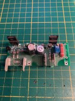
Attached is a picture of one of the quick and dirty prototype boards i did. This was Early 2019 this board was thrown together in under an hour as PCB's are cheaper than Veroboard.
I think i tried some different parts, BC548B and BC550C(Philips because of its low base resistance and noise)
Because i wanted to evaluate the circuit for low current heaters. I found a more linear transistor. The Toshiba 2SC4793 right about 2mA IB in the curves the early voltage is enormous. I also figured i could add a little 5mm pitch electrolytic
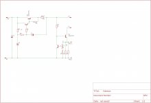
This schematic differs from the one i found online, in that it has a 25 turn pot for the current adjustment, i couldn't be bothered to fiddle around with parallel resistors to set the current, i know that this likely increases the impedance of the current source somewhat. But that was besides the scope of what i was trying to find out at the time.
I figured these kinds of circuits where more applicable to battery tube fillaments because those have low enough thermal mass to heat up quickly.
If i recall correctly at the time i thought the thermal stability was rather poor, i tested this whit a hot air soldering station. i think i tried a version where i put a 1N4148 diode in the emitter lead to compensate for the approximately -2mV/K shift in VBE of T1.
I did a evaluation of some of the publicly available schematics found in Guido Tents topic.
Attached is a picture of one of the quick and dirty prototype boards i did. This was Early 2019 this board was thrown together in under an hour as PCB's are cheaper than Veroboard.
I think i tried some different parts, BC548B and BC550C(Philips because of its low base resistance and noise)
Because i wanted to evaluate the circuit for low current heaters. I found a more linear transistor. The Toshiba 2SC4793 right about 2mA IB in the curves the early voltage is enormous. I also figured i could add a little 5mm pitch electrolytic
This schematic differs from the one i found online, in that it has a 25 turn pot for the current adjustment, i couldn't be bothered to fiddle around with parallel resistors to set the current, i know that this likely increases the impedance of the current source somewhat. But that was besides the scope of what i was trying to find out at the time.
I figured these kinds of circuits where more applicable to battery tube fillaments because those have low enough thermal mass to heat up quickly.
If i recall correctly at the time i thought the thermal stability was rather poor, i tested this whit a hot air soldering station. i think i tried a version where i put a 1N4148 diode in the emitter lead to compensate for the approximately -2mV/K shift in VBE of T1.
Attachments
Last edited:
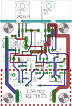
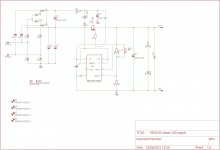
Fixed version.
I found two bugs in the PCB, Appearntly eagle footprints for some parts are just plain wrong, LM337 had pin 2 and 3 reversed, and because D1 was reversed, nothing happened.
Here is the fixed version, Enjoy.
Old PCB's can be made to work by shorting the diode between the adjust and cathode of the TL431.
Remove IC1 (LM337) and Short D1.
That way you cut out the pre-regulator, and are left with a regulator with slightly decreased performance.
Attachments
One thing I can say about Guido Tents circuit is it works. And it works damn good. I have pair of his boards heating my 300B SET amp. And I have it hooked to a pair of La Scalas @105db spl and I can't even tell if the amp is on by sticking my head in the speaker box. And it sounds amazing. And before anyone claims I am blowing smoke anyone in my area is welcome to come see for themselves. I am in Corvallis Oregon.
So just because some other person who presumably has a engineering degree and lots of fame in the DIY community couldn't get something to work this circuit is automatically garbage?
Then you invoke the forum rules, which you also broke by threadjacking Guido tent's topic on the same matter. New DHT heater
Instead i post something with the schematic so others can improve upon it, or give valid criticism in the spirit of DIY.
Everytime i post something on the matter, you come in and bite my head off. I would get defensive too when i'm selling something at a 400-900% margin.
Ive had it with this boomer enclave and its entrenched interests.
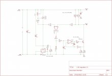
This is pretty close to the innards of a tentlabs regulator, at least the early versions, the LM337 and TL431 and clamping diode was my own idea the rest is more or less borrowed. the reasons behind this at the time was to add a current limit, and fix some of the precieved flaws in the tentlabs system.
I have a couple of friends who use these, and sold a couple. But ive moved on to different things,
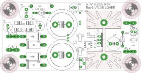
One of which was a low drop regulator that will provide 6.3VDC from 6.3VAC works really well, just a PITA to solder because of all the SMD. Boardfiles attached
I have a couple of friends who use these, and sold a couple. But ive moved on to different things,
One of which was a low drop regulator that will provide 6.3VDC from 6.3VAC works really well, just a PITA to solder because of all the SMD. Boardfiles attached
Attachments
- Home
- Amplifiers
- Tubes / Valves
- DHT heater supply design