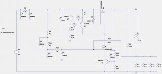
Ok here it is, the unregulated supply with better output impedance than capacitance multiplier, and lower Vdrop (around 1.5V)
Maybe not as good as your one Mark but still very good.
PSRR is 80dB at 100Hz
Output impedance is below 1 mOhm 20Hz to 20kHz which is excellent.
Please test circuit with lab powersupply first to check Vdrop is maintained with changing Voltage Input.
Selection of M2 is critical it works with this lateral mosfet it doesn't work with IRFP240, ie it doesn't track the voltage correctly with constant Vdrop.
There maybe other suitable mosfets eg mosfets with low transconductance I suspect may work also.
Attachments
Congratulations on your success!
The schematic in #341 might turn out to be only a "rough draft," with refinements and adjustments coming along later. For example, base resistors R6 and R9 might end up significantly greater than 10 ohms. D1 might someday become a Zener diode, which neatly clamps VGS_on to 12 volts, and also clamps VGS_off to -0.7 volts. The series combination (R18 + R3) might grow to be much larger than the pre-loading resistor R2 -- or, they might replace it entirely. Whatever tweaks & twiddles you decide to put in or to take out. Maybe you'll even take out the Rush Cascode (NMOS source connected to PNP emitter), if that eliminates the dependency upon one specific lateral MOSFET.
You've discovered that negative feedback is a magical ingredient, which noticeably reduces output impedance: Zout_closedloop = Zout_openloop / (1 + loop_gain) . Just as the textbooks claim.
_
Last edited:
Just as the textbooks claim.
_
I guess those bloody text books are occasionally useful.
😀
I could be convinced to buy one.
Last edited:
Member
Joined 2009
Paid Member
did you eventually find a use for this regulated supply in building a Pass Amp ? Regulated supplies don’t seem to be very popular.
I kind of feel a cap multiplier is the best compromise between performance and being dumb simple.
I am still trying things out though.
I will be trying everything in an amp I have built and deciding what is an audible improvement and where it stops being audible.
I am still trying things out though.
I will be trying everything in an amp I have built and deciding what is an audible improvement and where it stops being audible.

Actually there is. PCB design is virtually complete.
I need to get off my **** and finish the last remaing changes.
I need to get off my **** and finish the last remaing changes.
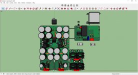
I know I am missing something but 188000 mfd up front does provide a some what stiff supply on it own ? How much modulation are we looking at? Forgive me if these question have all ready been ask . My point if the front is stiff enough then the impedance of the unit after that is what will effect the amp by means of the positive feedback loop that is the power supply .Ok here it is, the unregulated supply with better output impedance than capacitance multiplier, and lower Vdrop (around 1.5V)
Maybe not as good as your one Mark but still very good.
PSRR is 80dB at 100Hz
Output impedance is below 1 mOhm 20Hz to 20kHz which is excellent.
Please test circuit with lab powersupply first to check Vdrop is maintained with changing Voltage Input.
Selection of M2 is critical it works with this lateral mosfet it doesn't work with IRFP240, ie it doesn't track the voltage correctly with constant Vdrop.
There maybe other suitable mosfets eg mosfets with low transconductance I suspect may work also.
- Home
- Amplifiers
- Pass Labs
- Developing a Regulated Dual Rail Power Supply For FirstWatt Amps