Developing a Regulated Dual Rail Power Supply For Pass DIY Amps
Why did I choose bipolar transistors?
1) Smaller voltage drop across transistors compared with mosfets, which means less heat generated/wasted
2) A larger variety of suitably matching npn and pnp devices
3) I have a stack of bipolar transistors in my stash of parts that will probably never be used in an amp circuit.
I have not had the chance to test this circuit in the lab as yet, and would appreciate advice on improvements that aren't radical changes to the original circuit.
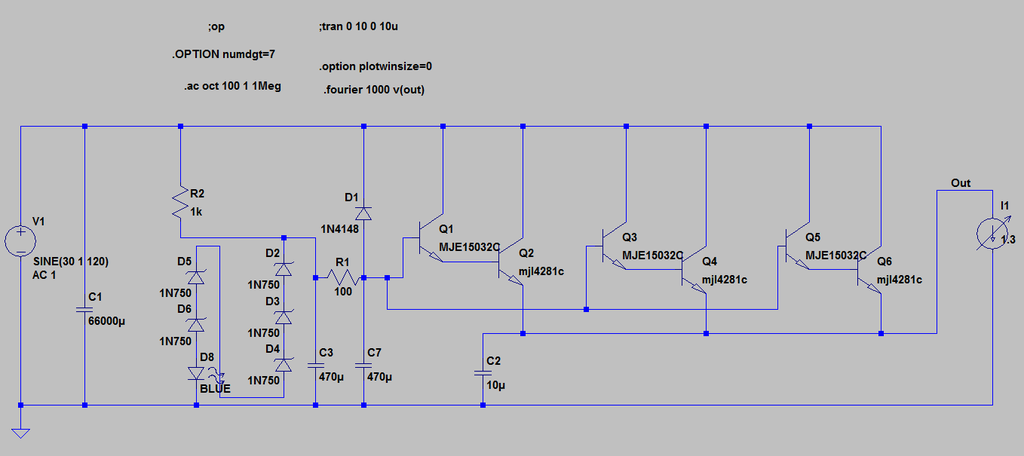
Here is the positive half of the circuit
Sorry about photobucket no longer showing images.
I will update here later with full documentation eg pdf or similar
Why did I choose bipolar transistors?
1) Smaller voltage drop across transistors compared with mosfets, which means less heat generated/wasted
2) A larger variety of suitably matching npn and pnp devices
3) I have a stack of bipolar transistors in my stash of parts that will probably never be used in an amp circuit.
I have not had the chance to test this circuit in the lab as yet, and would appreciate advice on improvements that aren't radical changes to the original circuit.
Here is the positive half of the circuit
Sorry about photobucket no longer showing images.
I will update here later with full documentation eg pdf or similar
Last edited:
me not likee when phase is changed
put BF245C in place of R2
ya still need TES device on output of circ
put BF245C
in place of R2ya still need TES device on output of circ
me not likee when phase is changed
put BF245C
ya still need TES device on output of circ
Yeah I wasn't sure about whether that would be a problem or not, but decided to use it to my advantage.
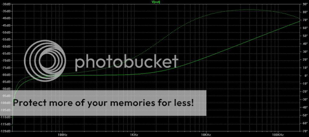
With CCS performance is flat but not as good.
I'll do a sim.
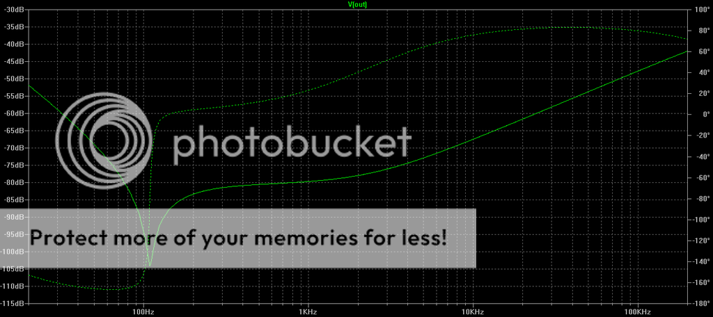
Gain and feedback will lower the impedance and increase the line rejection ("ripple reduction") at DC and at low & midrange frequencies. Some people are frightened of gain and feedback.

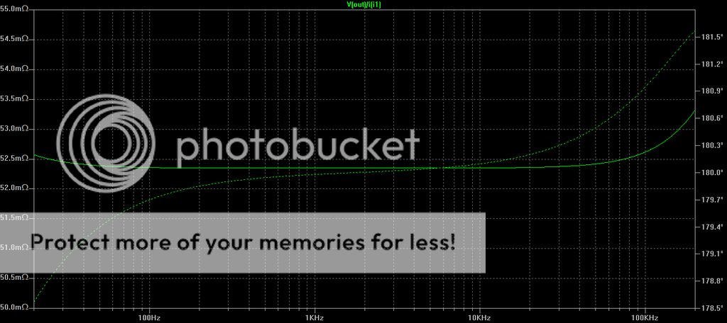
I got output impedance down to 23mOhms by a very simple tweak.
I think I am more than satisfied with that.
I think I am more than satisfied with that.
The circuit which you posted only for one channel ?. OR need to add more out put devices for stereo set up ?.
All will be revealed.
You could run two channels off it, but I plan to do dual mono or semi dual mono.
You could run two channels off it, but I plan to do dual mono or semi dual mono.
Given that most people are usually satisfied by a CRC supply I'm starting to think that the highest priority here is ripple reduction, followed by decent output impedance, with regulation being at the bottom of the priority list. So I'll also do a straight Capacitance multiplier supply as well, which has the advantage of an even smaller voltage drop.
Just thinking out loud.
I'll post up all the potential circuits
Just thinking out loud.
I'll post up all the potential circuits
What about a cap multiplier with a mosfet but adding a battery in the 3 to 6v range in series with the gate . This way you could have the voltage on the gate about 3 volts higher than the drain voltage so you wouldn't lose but a volt or so in the mosfet.
you need bloody reservoir cap on output
build it , then listen with and without
then choose
I have held off from doing that because you get a rising impedance response with decreasing frequency ie higher impedance in bass region as opposed to flat impedance.
If I add a reservoir cap it's gonna be 200,000uF to reduce this effect. Do you think there will be any problem with such a large capacitor on output?
I'm quite happy adding more bipolar transinstors if require.
Burning Capacitance Multiplier 1
Hahahaha
- Home
- Amplifiers
- Pass Labs
- Developing a Regulated Dual Rail Power Supply For FirstWatt Amps