I'm wondering if a separate low power SSR could be used to essentially isolate the short sensing circuitry when not in use. Basically put at least one end of it in a high impedance mode.
Such SSR wouldn't need to switch any power at all, with the tiny currents at work when in use, and then once isolated by the SSR, the speaker signal couldn't come to harm this low powered circuitry.
Some clamping diodes could still be strategically placed to prevent any kind of unwanted stuff.
A comparator could still be powered off the power amp's rails, while the microcontroller's I/O could be fully isolated from it all via optocouplers. Plus the SSR to render it inert when not needed.
Yes, ground lifters are a good thing to use, and not much to add really.
But what I'm really curious about is how effectively a contact from that positive can actually be possible, if the output plug is right there on the PCB. What could be done to put that positive output signal to chassis, by what path?
Having no wiring at all between the positive and the plug, I don't see what could come in to make any contact.
I use the Neutrik SpeakOn plugs, PCB mounted. So I'm wondering how this situation could be even possible.
It’s on the outside of the amp. If you short the + to the chassis - say to a bolt or screw - it’s the same as a short to 0V. It might be you assess that as low risk, but it’s possible and the user should be made aware. If the amp output has failed to one of the rails putting DC out, that’s also a failure mode to consider.
Neutrik connectors are very good so I think the risk is very low. In my case I always use binding posts.
I've been toying with a few ideas in simulations.
So far nothing much came out of it, with most not really going in the right direction.
Most of the stuff should remain as discrete and not make use of ICs, to avoid any need for additional supplies for the low voltage stuff, and just make use of the power amp's rail voltage, whatever it might be.
A PIC (or whatever uC) can send its signal via a photovoltaic coupler, insuring galvanic isolation, and this needs a bit of additional circuitry around it to protect it from the high signals from the power amp when it's operating, and not offer any kind of disturbing load to the amp, to keep things clean.
The resulting output signal from the detection of shorts can be fed back to the PIC via an optocoupler again.
I figured the signal from the PIC coming via the photovoltaic coupler could be split into 2 legs with 2 dividers, one serving as the reference, the other having the speaker line as part of it.
Then those 2 signals fed into a discrete comparator, before going via optocoupler back to the PIC.
I tried playing with hysteresis on the comparator a bit, but nothing came out of it that I found useful.
Now what would be needed is that kind of "sync-det" gating to the comparator, which could be done with some AND function using the stimulus signal to gate the comparator's output.
That's the part I have yet to figure out.
In the simulation (see attached), I just put a voltage source posing as the photovoltaic side of the coupler that would get the stimulus signal from the PIC.
That requires that protection circuitry against the large signals from the power amp while it's operating normally, which isn't there in that sim.
Also more such protection is required for the rest of that sensing and comparing stuff to make it all impervious to the large signals.
Basically, the PIC sends a stimulus via photo-coupler, and then gets something back also via a coupler. All galvanically isolated from the amp, and the stuff connected to the amp needs clamping stuff to prevent damage from big signals.
Now it's time to start punching holes into my "theories" applied here, and come up with some way to gate the response signal with the stimulus.
This would not need any extra supplies, remain all discrete and hopefully the part count can remain low as well.
That stuff remains connected at all times to the amp, so it should not only never be bothered by whatever the amp is doing when operating, and also not bother the amp and cause distortion.
Can someone offer more clever solutions?
Attachments
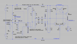
One thing wrong in that sim posted earlier that I'm wrestling with, is how to cope with the large signals from the amp while operating with those resistor dividers being directly connected to the amp's out. Namely those R1,7 & 8, being in parallel with the speaker and directly on the amp's output. I don't see any way to protect this from the large signals.
Some better way is required.
Some better way is required.