Charlie_fd.... sorry, i have forgot.
Big condensers.... 2200uf and up, soldered into the board, very near the transistor colectors...from the rails to ground also will help.
But this will be perceived only near the distortion threshold...the clipping threshold.
220N in parallel with the drivers emitter resistance (180 ohms), will behave as suck out of charges during clipping.... will produce less annoying distortions only... really...well.... you know....no one is listening distortions...but perfectionists may need that.
regards,
Carlos
Destroyer X amplifier ...DX amp...my amplifier
Just a reminder to anyone who listens to their DX, or any other amplifier , at such high levels that clipping becomes audible,that you are at real risk of destroying your tweeters. !
Most wives will complain long before you get to this point anyway.
They are far far more sensitive to this than us mere males.
SandyK
Hi, Carlos!
Great daughter! I have daughter too... she is 4 years old")
I have started with PSU. I am wiring a transformer now... 25-0-25... -1,4(bridge) * 1,41(capacitors) = ~35V
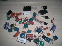
Today I bought already all parts for Dx one channel. 15euros spent... a lot for me, but low for that kind of amp
For PSU I will use Your schematics... except capacitors... I have 4x22000mF/42V and 2x33000mF/40V (my fathers present )
Great daughter! I have daughter too... she is 4 years old
I have started with PSU. I am wiring a transformer now... 25-0-25... -1,4(bridge) * 1,41(capacitors) = ~35V
Today I bought already all parts for Dx one channel. 15euros spent... a lot for me, but low for that kind of amp
For PSU I will use Your schematics... except capacitors... I have 4x22000mF/42V and 2x33000mF/40V (my fathers present
)Attachments

As you are wiring your trafo...try to have 29 plus 29 AC
this way you will have a little bit more power... also your electrolitic condensers will tolerate.
Beautiful girl you have...pretty eyes, good face she has.
Those condensers...specified as 40 volts..they do not explode when you make them work with 41 or 42 volts....there's a safe margin that you can use to your own benefits.
regards,
Carlos
Attachments

Using a little bit more voltage you will be able to have good peak power
this makes dynamic power a little bit more interesting too.
The output, single pair, cannot hold full power for too much long time..say, continuous tone and full undistorted power for too much long time.
But as music is not continuous, you can use this peak power.
As you will be winding your transformer, you can produce the option of 25, and 29 volts tapes.
This power can be produced, over 4 ohms...... and 75 Watts RMS when driving 8 ohms loads.
This will not make the amplifier play loud... that difference is almost nothing to our ears... but.... you will have lower distortions, as it will be able to reach 75 watts during peaks without clip...this turns sound better to our ears.
regards,
Carlos
...............................................................................................................
Yes Sandy
When we go to clipping, the waveform turns into square...those waveforms have a lot of harmonics.... exactly those harmonics will kill the tweeter.
thank you, good to remember that.
regards,
Carlos
Attachments
That's the boards drilled, a test heatsink prepared too
Quick question.
I know earthing was covered earlier in the thread but the replies became a little confusing so:
PSU earth to board at GND
Zobel Earth to somewhere on the board. GND or ELink or doesn't really matter which ?
Speaker ground, from the PCB, but is there a preferred place to connect to ?
Quick question.
I know earthing was covered earlier in the thread but the replies became a little confusing so:
PSU earth to board at GND
Zobel Earth to somewhere on the board. GND or ELink or doesn't really matter which ?
Speaker ground, from the PCB, but is there a preferred place to connect to ?
Short length and heavy gauge wire...not too much.... 1.5 milimeter diameter
will bring the transformer center tape connected to ground with screw, solder or do something that guarantee good contact.
This can be done near the board, or under the board, into the metal plate you have under the board....the lower cover of your enclosure.
Also the central point can be near the transformer...also in the back panel..well..small distance and central point.... the point were all ground wire goes.
then run short length wires from the board grounding points to this central point.
This is the method i use...everybody going to the same point..short length, heavy gauge wire.
But there are people better than me in those things.... let's keep thread opened to them to correct my method, to include repairing details or to suggest other better option.
You have an input lifted ground in your circuit board...the 10 ohms resistance is connected to this central ground in one of it's extremes and the other one will constitute into your lift ground....there you will solder the 220 picofarads RF capacitor, the 39K resistance, C10 and C11.... do not worry, as this was made into the circuit board...just observe that one of the grounding points are one of the 10 ohms extreme...the free side, the one not connected to the parts i am refering..
You have two E links to connect using a wire jumper...they will join the rail filter condensers to the ground (central, general standard ground) and you will need to run a wire from the zobel to ground.. the free extreme of C17 will have a wire connected to ground.
regards,
Carlos
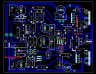
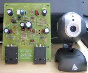
Dx amplifier... a very small board and a great sound
Enjoy Dx amplifier folks.
Cheers!
Carlos
...............................................................................................................
I was trying BD139 and BD149 as drivers....and they have worked.
relax and be happy folks!
regards,
Carlos
Enjoy Dx amplifier folks.
Cheers!
Carlos
...............................................................................................................
I was trying BD139 and BD149 as drivers....and they have worked.
relax and be happy folks!
regards,
Carlos
Attachments
All rigth...you can join Elink+ and Elink- ...but perceive they are already
joined into the copper lines.... they travel till the Gnd point... Ze ground point is the one was not connected... to use a small piece of wire to central ground point..or even to travel, under the board to the Gnd or other nearest point.
The GND mark and also Ze mark are grounds.
In the Dx board, the one offered into the home page, we have to solder a jumper into points Elink+..... connecting those two holes...and also solder a jumper into points Elink-.... connecting also those other two holes.
Yes...you can make it already joined into your design...this was make to offer other grounding options.
regards,
Carlos
Attachments
Re: Here is one idea.
Pictures yay ! I like pictures. Thank you
So Zobel and speaker directly back to the star earth. That will do nicely.
Completed board picture too, nice. I need to get my 100n to lose some weight <chuckle>. I'll just hide them on the back of the board.
destroyer X said:
this may turns construction easy.... i have made this way and no problems, noises or anything bad.
Having two channels, you will need more wires.
regards,
Carlos
Pictures yay ! I like pictures. Thank you
So Zobel and speaker directly back to the star earth. That will do nicely.
Completed board picture too, nice. I need to get my 100n to lose some weight <chuckle>. I'll just hide them on the back of the board.
Under of over it will work fine...make it the way you want my friend.
It will sound nice..even under the board.
hehe.
regards,
Carlos
.................................................................................................................
Dx Corporation important crew members wishes you the best luck.
regards,
Carlos
It will sound nice..even under the board.
hehe.
regards,
Carlos
.................................................................................................................
Dx Corporation important crew members wishes you the best luck.
regards,
Carlos
Attachments

Re: Here is one idea.
Where does earth from mains go?
destroyer X said:
this may turns construction easy.... i have made this way and no problems, noises or anything bad.
Having two channels, you will need more wires.
regards,
Carlos
Where does earth from mains go?
Computer heatsinks?... depends the one... will you use fan blower.
this will be needed Microp
Without fan blower...... only if your environment temperature goes lower than 5 degrées celsius.... i think you have not that low temperature inside home.
Needing some..... just call me.....and please, having time, produce images and post them to us.
regards,
Carlos
.................................................................................................................
Nordic.
I think the chassis will be a good point to connect your mains ground.
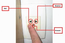
I have three wires in my place.... phase, neutral and ground.....one is alive having 220 Volts - 60 hertz...other is neutral and not good to grounding, of course.... the third one is connected to a one inch cable that goes down the building and enter the ground with a lot of parallel ones, made by 10 feet long copper bars, entering deep into the ground.
The ground received Carbon and some salt....the soil was treated and receive some humidity...it is a very low resistance ground.
This ground is connected to my computer, as my mains outlet use 3 pin plugs..alike computers.
regards,
Carlos
this will be needed Microp
Without fan blower...... only if your environment temperature goes lower than 5 degrées celsius.... i think you have not that low temperature inside home.
Needing some..... just call me.....and please, having time, produce images and post them to us.
regards,
Carlos
.................................................................................................................
Nordic.
I think the chassis will be a good point to connect your mains ground.
I have three wires in my place.... phase, neutral and ground.....one is alive having 220 Volts - 60 hertz...other is neutral and not good to grounding, of course.... the third one is connected to a one inch cable that goes down the building and enter the ground with a lot of parallel ones, made by 10 feet long copper bars, entering deep into the ground.
The ground received Carbon and some salt....the soil was treated and receive some humidity...it is a very low resistance ground.
This ground is connected to my computer, as my mains outlet use 3 pin plugs..alike computers.
regards,
Carlos
Attachments
- Status
- Not open for further replies.
- Home
- Amplifiers
- Solid State
- Destroyer x Amplifier...Dx amp...my amplifier