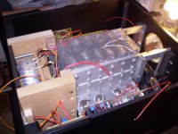
The super hiper very important coil is here.
I could perceive something in treble range...also bass looks better...maybe my imagination....i am not those unobtanium RCA plugs chromium finishment believer..sorry.
There are two.... one each rail..yes i know i could have used only one.
The coil was not shown by the picture, because too ugly..coiled over a ferrite core.
The resistance i have used in the schematic is a 5 watts unit, those rectangular white ones....you can increase your turns number, but check if resistance is lower than 0.1 ohms
* Unobtanium, unexistenium,phoolingU is from Audiophool thread opened by stormy fellow Mikeks....thread moved...he is terrible!...but i like him very much..he is not bad..has good heart.
regards,
Carlos
Attachments
I think it is fine...mine was not calculated, not designed.
I have copied informations from many guys....joined together resulted this one published.
People have told me those fast recovery diodes are very good.
Thank you Ostry.
regards,
Carlos
I have copied informations from many guys....joined together resulted this one published.
People have told me those fast recovery diodes are very good.
Thank you Ostry.
regards,
Carlos
Attachments
Excelent number.... if distortion is fine
Thank you...cooperation is always good, to know friends that are hitting forum counter is also nice.
And you have already visited....returne because have apreciated the place....welcome to you.
find a chair or a place into the sofa, make yourself confortable, this place is yours.
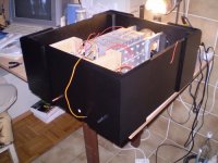
The supply filtering is very important to the quality...but i think related the power is a little bit less important..beeing the transformer power more important...my transformer, for instance, can loose 4 volts when i need current..voltage goes to 33 when the amplifier is having 6 amperes of consumption...not very good.
That transformer was "saved" from a Panasonic System..and that one was not very powerfull....maximum 50 watts each channel... so..things makes sense.
regards,
Carlos
Thank you...cooperation is always good, to know friends that are hitting forum counter is also nice.
And you have already visited....returne because have apreciated the place....welcome to you.
find a chair or a place into the sofa, make yourself confortable, this place is yours.
The supply filtering is very important to the quality...but i think related the power is a little bit less important..beeing the transformer power more important...my transformer, for instance, can loose 4 volts when i need current..voltage goes to 33 when the amplifier is having 6 amperes of consumption...not very good.
That transformer was "saved" from a Panasonic System..and that one was not very powerfull....maximum 50 watts each channel... so..things makes sense.
regards,
Carlos
Lol, oh well still enough to blow some speakers... ever put a thin wire between a 9v battery's terminals?
Had a real good day, wife went to the mall with a friend.
And I went to the fleamarket, had a ball.
One guy had a scratch patch of old tools and bits like hole taps, manual drils, files you name it, tonnes of hand tools for 1R each. thats about a tenth of a dollar in the real world...was realy oily and messy... oh what fun... got some small spanners, a very nice figure saw for metal... not the flimsy crap you get everywhere... a small component rack with 8 drawers for $2, some countersink drill bits to sink screw heads in wood... 1R each etc...
Then I came home and played with Greg's assignment of the power bar switcher... not done, but makeing good progress on the layout side... then I have to teach myself to programme again, hope to get that done tommorrow, as I also have a big job assignment this week....
Attachments
Something else I played around with... an output powered, power level indicator....
It lights up as follows
8 ohm load 2W, 5W, 10W, 20W, 40W, 80W
4 ohm load 4W , 10W, 20W, 40W, 80W, 160W
http://www.redcircuits.com/Page102.htm
It lights up as follows
8 ohm load 2W, 5W, 10W, 20W, 40W, 80W
4 ohm load 4W , 10W, 20W, 40W, 80W, 160W
http://www.redcircuits.com/Page102.htm
Attachments
Nordic said:One guy had a scratch patch of old tools and bits like hole taps, manual drils, files you name it, tonnes of hand tools for 1R each. thats about a tenth of a dollar in the real world...was realy oily and messy... oh what fun... got some small spanners, a very nice figure saw for metal... not the flimsy crap you get everywhere... a small component rack with 8 drawers for $2, some countersink drill bits to sink screw heads in wood... 1R each etc...
Then I came home and played with Greg's assignment of the power bar switcher... not done, but makeing good progress on the layout side... then I have to teach myself to programme again, hope to get that done tommorrow, as I also have a big job assignment this week....
Hi Nordic,
Sounds like you scored some good stuff.

Excellent work on the power bar switcher. I've been thinking about it for years and you go and do half of it in a day. Are you trying to show me up?
Well, I'd better go and build the case for my DX Amplifier.

regards
Lol Greg, new brooms and all that, but in all seriousness, it is a handy project...
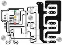
I have now finished the PCB layout... allthough I'm toying with the Idea of seperating the relay board from the controler board... which causes as much trouble as is it saves.... probably won't... but I might add limiting fuses still...
Also In concept it has 4 buttons,
1 start/stop sequence
2,3,4 for each relay
Program concept... (programme erased when standby mode interupted - will deault to default programmed seconds then)
All 4 buttons in activates programe mode
LEDS flashes then LED for relay one and two lights. At which point, you use buttons 2-4 to select delay from 10 to 30 seconds... LEDs flash, LED 2 and 3 light up, followed by previous programmeing sequence.
button one - power on function
red led lights and relay 1 on, delay, orange LED and relay 2 on, delay, green LED and relay 3 on.
Button one - power off function
Reverse sequence above + flashing standby, untll all off then, solid standby LED
Button 2 - 4 to switch off individual relay...
Attachments
Dx amplifier home page is beeing updated daily.
Please, give us the honor of your visit once more.
Now we have the power supply and the supply parts list too.
Home page is turning better.
http://users.tpg.com.au/users/gerskine/dxamp/
regards,
Carlos
Please, give us the honor of your visit once more.
Now we have the power supply and the supply parts list too.
Home page is turning better.
http://users.tpg.com.au/users/gerskine/dxamp/
regards,
Carlos
Carlos, Greg and others involved,
Great project, very well engineered, beautiful website, good vibrations and a lot of good, free advice to amp enthusiasts!
Be careful - your back up service will soon be better than mine and you will not be able to sleep!
Like the power supply....
Cheers,
Hugh
Great project, very well engineered, beautiful website, good vibrations and a lot of good, free advice to amp enthusiasts!
Be careful - your back up service will soon be better than mine and you will not be able to sleep!
Like the power supply....
Cheers,
Hugh
I was remembering you those last days because of that Hugh.
And i could understand better why you jumped out from Kits production, into already builded units.
Doubts are unlimited, as each one has different experiences..and this takes time, to stay over the builder's shoulders controling everything.
regards,
Carlos
And i could understand better why you jumped out from Kits production, into already builded units.
Doubts are unlimited, as each one has different experiences..and this takes time, to stay over the builder's shoulders controling everything.
regards,
Carlos

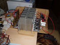
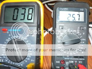
Yesterday i finally had some time to investigate the vbe-multiplier Carlos proposed.
The second 1k resistor is shorted, used transistor is bd139 .
I couldn't get it to work with 2k resistor, after changing to 1k it seems to work fine.
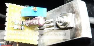
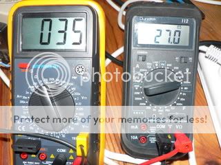
Biased high at ~120mA , left is temperature of heatsink, right is voltage across rail-resistor (0.22 ohms).
The dynatek shows low-battery signal from monitoring too long , don't worry, the voltage shown is accurate.
Heatsink used is the small one i used before, 0.87 c/w.
Drivers used heatsinks too.
Measurement taken after > 1 hour , ambient-temp is 22 degrees celsius.
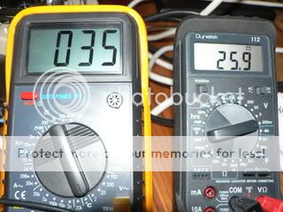
To test something, you have to throw bricks at it.
The brick i used was a 800 watt hairdryer, i heated up the main heatsink:
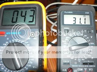
There is a little overshoot in bias, because i mounted the vbe-multiplier at the mounting-bar for the outputs.
When i heated up the heatsink the mounting-bar took a little more time to heat up.
Under normal circumstances the heat will come from the outputs,
this will cause the mounting-bar to heat up quicker than the main heatsink,
providing fast thermal tracking.
Cooling down:
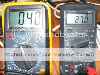
........
Back to normal:
The vbe-multiplier seems to provide excellent bias-control,
the channel under testing is now running at ~120mA bias continuously for more than a day.
This is not a bias-level i would recommend to others,
i just use it to see if the vbe-multiplier performs under these circumstances.
The DX-amplifier is, literally, still cooking
Best regards,
Klaas
The second 1k resistor is shorted, used transistor is bd139 .
I couldn't get it to work with 2k resistor, after changing to 1k it seems to work fine.
Biased high at ~120mA , left is temperature of heatsink, right is voltage across rail-resistor (0.22 ohms).
The dynatek shows low-battery signal from monitoring too long , don't worry, the voltage shown is accurate.
Heatsink used is the small one i used before, 0.87 c/w.
Drivers used heatsinks too.
Measurement taken after > 1 hour , ambient-temp is 22 degrees celsius.
To test something, you have to throw bricks at it.
The brick i used was a 800 watt hairdryer, i heated up the main heatsink:
There is a little overshoot in bias, because i mounted the vbe-multiplier at the mounting-bar for the outputs.
When i heated up the heatsink the mounting-bar took a little more time to heat up.
Under normal circumstances the heat will come from the outputs,
this will cause the mounting-bar to heat up quicker than the main heatsink,
providing fast thermal tracking.
Cooling down:
........
Back to normal:
The vbe-multiplier seems to provide excellent bias-control,
the channel under testing is now running at ~120mA bias continuously for more than a day.
This is not a bias-level i would recommend to others,
i just use it to see if the vbe-multiplier performs under these circumstances.
The DX-amplifier is, literally, still cooking
Best regards,
Klaas
Oh!...this made a relief in my heart...i was sick inside myself because your problem
Those things are strange, as i had mine one stable.
I see that things are running perfectly now.
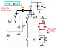
I have a small suggestion to you....install a 220n or 100N capacitor into the points shown in the schematic.
Also, if you wanna treble boost, having not this adjustment
in your pré amplifier or sound source, install 33n to 150n capacitor as shown.
The TIP41 as driver use to loose treble.... very sligtly... this
is the main difference you may have using low speed transistors....the problem is not quality, but level only...compensating, dinamically, you will perceive everything
flat.
I am not telling you about graphics,... the amplifier is flat when testing...but listening, real world audition, some small losses in the high end can be perceived because of the low speed transistors used to make the amplifier simple and cheap...just try that if your transistors are not high speed.
The other 100n, installed at the differential long tail is for stability purposes.
regards,
Carlos
Those things are strange, as i had mine one stable.
I see that things are running perfectly now.
I have a small suggestion to you....install a 220n or 100N capacitor into the points shown in the schematic.
Also, if you wanna treble boost, having not this adjustment
in your pré amplifier or sound source, install 33n to 150n capacitor as shown.
The TIP41 as driver use to loose treble.... very sligtly... this
is the main difference you may have using low speed transistors....the problem is not quality, but level only...compensating, dinamically, you will perceive everything
flat.
I am not telling you about graphics,... the amplifier is flat when testing...but listening, real world audition, some small losses in the high end can be perceived because of the low speed transistors used to make the amplifier simple and cheap...just try that if your transistors are not high speed.
The other 100n, installed at the differential long tail is for stability purposes.
regards,
Carlos
Attachments
Juan, from Galícia, Spain, have asked me how to reduce his supply
....voltage from 63 to 36 volts to use into Dx amplifier.
Here is the schematic Juan.
The transistors are Darlingtons, TIP142 and TIP147...use two in parallell.
The NPN transistor is TIP41
The PNP transistor is TIP42
Condensers, all them, with 75 volts or more of maximum workable voltage.
The trimpot will be able to adjust voltage.... supplies from 45 to 63 can use this schematic without modifications.
The Output Darlingtons will need a very big heatsink..as they will dissipate enormous power if your supply keep this 63 Volts without too much losses.
Well...at least you will have a variable output voltage supply.....reasonably stabilized (5 percent).
regards,
Carlos
Attachments
Juan, from Galícia, Spain, have asked me how to reduce his supply
....voltage from 63 to 36 volts to use into Dx amplifier.
Here is the schematic Juan.
The transistors are Darlingtons, TIP142 and TIP147...use three in parallell to each rail.
The NPN transistor is TIP41
The PNP transistor is TIP42
Condensers, all them, with 75 volts or more of maximum workable voltage.
The trimpot will be able to adjust voltage.... supplies from 45 to 63 can use this schematic without modifications.
The Output Darlingtons will need a very big heatsink..as they will dissipate enormous power if your supply keep this 63 Volts without too much losses.
Well...at least you will have a variable output voltage supply.....reasonably stabilized (5 percent).
Zener diodes can be 1 watt units to run cold.
Supply dimensioned to hold two channels operating 4 ohms
regards,
Carlos
Attachments

Hi Carlos,
The capacitor across R10 in post#977 could maybe have a small resistor in series with it; possibly of a value = R10 divided by between 5 and 10.
If R10 was a poteniometer, with the additional C connected between the slider and one end, the adjustment could be made pre-settable or variable.
Cheers .......... Graham.
- Status
- Not open for further replies.
- Home
- Amplifiers
- Solid State
- Destroyer x Amplifier...Dx amp...my amplifier