Fair Weldon, a public message, you are the one and leave inside my heart, thank you.
thank you by the fast remotion of the post i have asked you to delete...my bad post, that created problems.
What happened was explained to you, and fast you have helped me Weldon
Happened with me, that a dear friend, someone that i use to talk daily, sometimes 3 to 4 times a day turn angry with me because that image i have post.... using a German helmet.... also US troops helmet too...but the moustache was from that bad guy...Adolph.... i was kidding, as we use to do, but was considered annoying by Mr. Sparkle... i think i have faced him with bad mood or i touched some open wound in his heart.
You fixed the whole thing...once again, your intervenction was needed, fast and fair.... Well Done as you even did.
Moderators are a need, as we make foolishes, we are not perfect...someone thinking on the forum needs must be supervising, and someone alike you is extremelly needed and precious.
No...i cannot forget that others use to make nice work too...SY, Planet10, Variac, Pinkmouse,Netlist and AudioFreak... all those, and others, helped me at least once.... Anatech had not too many chances to help me till those days, but i think he will be ready too if needed more times.
Well there are others to thank.
But i cannot forget to tell you that you are my prefered one.... 98 for others...you got my 100!
The story that moderators are not a need are enormous lye..also that we love everybody the same is another lye too.... we have our prefered ones...of course.
If we behave fine.... tracking over the rails..we will never face problems with moderators... the ones that made excesses, for sure, do not apreciate moderators very much....obvious reasons.
They are not bad...anyone of them...the opposite..if i try to find failure, to criticize something, i think they are good in excess...some bad folks deserve bad treatment and a kick in the....
regards,
Carlos
NP Carlos,with an active imagination, it is easy for the social acceptance part of our brains to fall asleep...but I also envy it because it leaves us in a more natural place than the selfmade boogiemen of our age does... one man can not be evil on such a scale... he needs the cooperation and blessing of thousands of others... something we kindly forget to make our view of the world hurt less...Does not matter where in the world it happens...
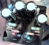
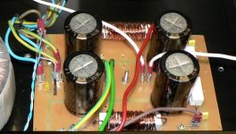
Back to the amp, here is the tp view of the PSU boards as promissed and requested by Klaas.
Back to the amp, here is the tp view of the PSU boards as promissed and requested by Klaas.
Attachments
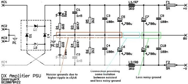
I adapted the psu-schematic adding some explanation.
PE-connection moved to the left (connection between center of caps and centertap of transformer)
Well this is what i think is best, people are welcome to shoot holes in my reasoning,
though i don't want to invite a discussion that drags on for days (done that a bit too often i'm afraid)
Your pcb ties everything together at a single point, creating a noisier ground.
Your pcb will most probably not create a humming amp, so no need to get upset about it.
It's also just my look at things.
Best regards,
Klaas
I am observing with attention...very interesting ideas.
Also the "vision" about earth segments, ground parts are very interesting.
I will need to make my reflections about.... i am a little confused how electrons will decide were is less confused ground or not...not kidding...i want to visualize...this is the best way to understand.
I use to make a movie inside my mind.
and i am doing.
Thanks kláas...nothing ironic or even sarcastic...serious.
Carlos
Attachments

Re. Power sup
Hi Carlos,
Bravo, It 's nice to see your power supply circuit. I have a problem with hum from AC line. I can only (A) change the grounding places (Power_in, sp_out. . .) to see the different and use the least noisy possible. In some instances, I have to (B) put additional wires to make loops in my ground node. I did (A) and (B) repeatedly until the noise went out and my amp is a sort of rug. Your design have taken away all these ugly stuffs. Nice moves.
Thanks.
DX power supply
I've tried the DX power supply on another power amplifier that's a well known and documented design (that shall remain nameless... and no, it's not an AKSA as that amp is perfect) and there were sonic benefits over the standard suggested 4 cap supply. The power amp became cleaner, better space around the vocals and instruments, tighter bass. The only difference was the use of 3n3 caps instead of 1n5 and 4K for the bleeders (that's what I had). I just modified an existing power supply so was quick an easy and well worth it, even though I don't totally understand it.
I (the secret other Aussie builder as Carlos put it") ) was going to build the DX amp as Greg was kind enough to offer me some PCB's to try but unfortunately I had to pull out of the Beta program as Cervical Spondylitis and Carpal Tunnel Syndrome (just found out about that one) has now made it difficult to do electronics on this scale. [Pick up resistor, drop resistor *@%& ]... you get the idea.
) was going to build the DX amp as Greg was kind enough to offer me some PCB's to try but unfortunately I had to pull out of the Beta program as Cervical Spondylitis and Carpal Tunnel Syndrome (just found out about that one) has now made it difficult to do electronics on this scale. [Pick up resistor, drop resistor *@%& ]... you get the idea.
Hopefully one day I'll get a chance to build and listen to the DX amplifier but there is still an Aussie building.... go Greg go.
I've tried the DX power supply on another power amplifier that's a well known and documented design (that shall remain nameless... and no, it's not an AKSA as that amp is perfect) and there were sonic benefits over the standard suggested 4 cap supply. The power amp became cleaner, better space around the vocals and instruments, tighter bass. The only difference was the use of 3n3 caps instead of 1n5 and 4K for the bleeders (that's what I had). I just modified an existing power supply so was quick an easy and well worth it, even though I don't totally understand it.
I (the secret other Aussie builder as Carlos put it
) was going to build the DX amp as Greg was kind enough to offer me some PCB's to try but unfortunately I had to pull out of the Beta program as Cervical Spondylitis and Carpal Tunnel Syndrome (just found out about that one) has now made it difficult to do electronics on this scale. [Pick up resistor, drop resistor *@%& ]... you get the idea.Hopefully one day I'll get a chance to build and listen to the DX amplifier but there is still an Aussie building.... go Greg go.
Attachments
Yes Nordic...this is the starting point..666 ohms to be easy to remember
Negative...this is not a magic mistery number...just a number easy to retain in the memory..could be 555 or 777 ohms too.
This will not be precise..it is a starting point only.
This resistance, this variable one, this trimpot, is connected from base to emitter, so, it will control the voltage developed to bias this transistor.... reducing this resistance your VBE will be reduced and the transistor will conduct less...the resistance from colector to emitter will be too much big.. as will increase....and this will create biasing problems.... voltage developed over a bigger resistance is a bigger voltage.
This VBE circuit is substituting a single 240 ohms resistance, having the advantage to be self adjustable when receive heat from the heatsink it is touching...overheating, the colector to emitter resistance goes down..the bias goes down to... as bias is this voltage needed to make the transistor turn on, and to work...let's say, in iddle speed...small current..but conducting..sorry..i cannot find words in english...marcha lenta
The zero ohms position will make a short circuit from base to emitter...and this will make the transistor turn off...turning off, the colector to emitter resistance will go to a very high value..the voltage that will be from colector to emitter, in the VBE multiplier transistor will be much higher than normal..and this will force drivers and output units to conduct more... the current will go to out space.
Increasing this base to emitter resistance, the trimpot, you will be biasing the transistor into conduction that will start above 500 milivolts (more or less)....beeing conducting..the resistance from colector to emitter turn lower, and this will develop lower difference of potential, lower voltage to bias the output devices...and them, adjusted to provide 2.4 volts from colector to emitter, you will make things work fine.
This way you will distribute four equal portions of 0.6V.... and each portion will bias each one of the output transistors.
How this will happens...automatically...each base to emitter can be understood as a diode...you have two diodes in series in the upper rail...the upper rail driver and the upper rail output transistor...each one of those base to emitter diodes will produce 600 milivolts...something alike a zener effect..injecting voltage.... the base to emitter junction will try to create 600 milivolts to be measured into those two leads.
The other transistor... the second one, will also produce 0.6 Volts...and this will be positive, and above the output line that is the "zero " volt reference point to the junction diodes...so.... the output transistor will have 600 milivolts from base to emitter and the driver will have also something alike...not so different....two times 600 milivolts will produce 1.2 volts...and this is positive...as output line is zero volts.
The lower transistors will do the same...each one of them with 600 milivolts (0.6V).... in this case you will have negative..as those diodes are referenced into the output line, and the way they are pointing will produce a less negative voltage than the output line....the result will be -1.2 Volts into the lower rail driver...measurement referenced by the ground...or the output line..as both of them has zero volts..in special when you install the speaker,a that has a very little resistance to ground...almost a short to ground.
So...the VBE multiplier will have +1.2Volts into the colector...and the colector will be connected into the driver base..so...as a consequence....driver base, to up rail, will have something near +1.2 volts too.
This VBE multiplier transistor (transference resistor) will have -1.2 Volts into its emitter......how?... already explained..... 2.4 volts will be produced when something alike 10 miliamps cross the colector to emitter resistance.... that 240 ohms equivalent.... to be continued in the next post.
regards,
Carlos
Continuing the explanation about the VBE multiplier.
BTW..it is called VBE multiplier because multiplies the 600 milivolts that you have form base to emitter into 4........ so..this will result in 2.4 volts.
continuing.....well.... that resistance will be enought to produce the needed voltage...and -1.2 volts will be into the negative rail driver transistor base.... because of diodes direction too...they are referenced into the output line (zero volts) and the diodes position will create the negative voltage you can measure referenced to ground...or output line..as both will be at zero volt potential.
Why 10 miliamps are crossing?
This is a matter of decision, and will fix the operational point to the VAS.... the result AC voltage generated in the VAS will be applied in the output, that will produce a gain in current...not a gain in voltage...the current will be multiplied by those transistor gains and will appear into the output.... both the upper rail half positive cicle and the negative rail half negative audio cicle.
The VAS, the voltage amplifier will provide you all the voltage you have in the output...it is a voltage without too much current..only 10 miliamps of iddle voltage... having a swing of something near to 50 volts peak to peak (I do not bother to be precise)... this will have a current amplification that drivers and output units will provide..but the output voltage is even lower than the drivers output voltages because to output losses.
The first resistance at the bootstrapp will reduce the upper rail voltage to 20 volts..or something around that..... Resistance R12, R13, Vr2, R14 and the VAS colector to emitter junction are in series..so...the current that is passing into a series of resistances will be the same.....and the VAS colector is connected into the negative rail driver base...and there we know that we will need -1.2 Volts...so...as the series of resistances are connected from the positive rail (slightly less... the rail resistance eat 2 Volts) to the negative rails...you can calculate the current there... reducing 2 volts to the positive rail resistor... 2 volts to the negative rail resistor and 1.2 volts that will be found into the lower end of this resistance in series..this train of resistances.....adding the ohms values...considering the bias resistances adjusted to something alike 300 ohms...more or less..you will see that the current..because ohms law.....74 volts (rail to rail voltage) less 5.2 volts (losses in rail resistances and because of VAS colector voltage) divided by the resistance will provide you the current...and will be around 10 miliamps.
R12, R13 and C2 are the famous bootstrapp...if this informations i am posting now was accepted, and if people ask..i can continue to explain the entire amplifier..within my limits of knowledge of course.
regards,
Carlos
Deeply honored with your presence Mr. Rabittz
Well...you know that my friendship, dedicated to you is very old...you were always very gentle.
I am deeply sorry about your disease..but it will be good in a matter of 40 days.
You will continue to produce your wonderfull speakers and the nice constructions to show us and cooperate with us....your hand motion will be perfect in a month and a half.
I am very happy that you have constructed and tested the Dx amplifier supply.... good to know your results...i am happy to know your acceptance related the supply.
Also very happy with your presence in this moment, here, with us.
Push a chair please...or sit on the sofa and stay with us..this will make us more rich with your presence.
A good spirit...a extremelly advanced man inside your soul.
If you do not know my other Aussie friend...here is a good presentation about the man.
http://www.rzaudio.com/design.htm
regards,
Carlos

Not needed to read the entire thread for that.
Just go to the home page...follow this adress here:
http://users.tpg.com.au/users/gerskine/dxamp/
Go to adjustments and follow the adjustment steps.
Do not need to read all my long and confused explications...read and adjust following step by step.
And then ready...you do not need to engage the whole brain's tired part..just the center brain part, dedicated to motion and front vision part... and them everything will be fine.
I know that when this time arrives you turn completelly exausted.
Another option is to order to my name air tickets.... going in one day and returning fligth to the next day...during you coffee break i will adjust to you...hehe...air tickets you pay!
be happy,
Carlos
Readings over the 10 ohms resistance can go from 500 milivolts till 1V.
This will mean currents from 50 to 100 miliamps.
The lower will be better to you...your environment is hot, your heatsink is not so enormous as we were dreaming...so....better to choice lower stand by current.
If you want me to fix the value for you.... than adjust the bias trimpot to read 600 milivolts into the positive rail and 500 milivolts into the negative rail.
The positive rail has that zener, and because of it, the positive stand by current is bigger than the negative.
Yeah..with those resistances in series, related the power rails..the measurement is made over the resistances.. i have published the sketch.... and was made to you and because of your doubts my dear.
The current is obtained using the Ohms law....you have to divide your voltage reading expressed in volts...so... 500 milivolts you may write as 0.5V...and the resistance have to be expressed in ohms..and it is 10 ohms (have you checked that?)
0.5 divided by 10 will result = 0.05A...this is 50 miliamperes.
Please, once again, visit the home page and read those instructions..also watch again the sketch i made.
After adjustments, remove the rail resistances, also remove the DC milivoltimeter you have attached to the output, remove the short you have made into the input... check if you have connected both rails....also check the ground wire if it is connected...connect the speaker, install series fuses into rails and into the output... inject the audio source into the input..switch power on and BE HAPPY man!
hehe..do not forget to smile, or call fire soldier if you let some wire power loosen, and the one touching the circuit will kill everything you have done...remember that soldered wires..all them..need an insulator..special insulator tape, scotch tape, band aid, paper corrugated adhesive tape...piece of paper around the connection, rubber bands, plastic tubes, pvc foil...well...something that can insulate...
Remove your damn cup of coffee out of your workbench, as liquid and electricity, together, and around is not a good idea.
Observe if your idiot dog is not trying to eat the mains power wire.
Dry that sweat out of your face..the result of stress, emotion and fear.
Remove the cat that is around your neck.
Ask your wife to talk at low volume, as you will inspect your amplifier.
Check if you metal glasses are well attached to your face...metal glasses falling over a circuit..when the constructor is so lucky as you are may be a problem.
Check the forecast to see if you will not have a ligthning tempest coming.
Banish your wife's mother because she may decide to stay for all nigth to listen the wonderfull Dx amplifier sonics...also observe some mouse... if he is around without turn too much nervous you may be a happy man..but, if the mouse tried to scape, showing that it is upset....than you have high frequency
oscilations...in this case, you have to increase the Miller capacitor value and pray for God help, as your weak Russian speaker will melt because you have delayed too much to power the unit off...ahahahahha!
regards,
Carlos
Attachments

- Status
- Not open for further replies.
- Home
- Amplifiers
- Solid State
- Destroyer x Amplifier...Dx amp...my amplifier