Here, you have the nice schematic Ecat made.
Also, having interest to assemble, search for Nordic, as he is developing boards and will tell you the last improved board he made.
Also Ecat is producing nice boards too, you have his option, in the reality they are producing boards into a cooperative system.... boards are almost the same...differences not huge.
You may have hundred doubts.... thousands of answers were posted, about doubts, please, read the forum thread...if something remain...if you still have doubts, post them into the thread or mail to me.
panzertoo@yahoo.com
regards,
Carlos
Attachments
Greg Erskine, one of our Aussie friends made a nice home page
All needed informs are there.
Into the forum thread, all possible doubts were explored.... i think any other new doubt will appear.
If this happens, after you read the thread, post your doubts.
But, in advance, please, take a look at the thread, it is long and detailed and i think you will find answers to your doubts there.
regards,
Carlos
Attachments
Pery,
Don't forget the Carlos amplifier design guide starting at Post #2840
http://www.diyaudio.com/forums/showthread.php?postid=1279670#post1279670
Nordic,
The board is looking quite the business. I was worried it would be to wide for me to use but it should be just about perfect.
Carlos,
My board is retired, use at own risk, watch out for some of the track clearence etc. Better that Dx Corporation concentrates on a single design for now.
I agree with reading the entire thread, there is a lot of good information here: design, assembly, testing, component choice and care, circuit building, soldering. The list goes on. It has grown into a comprehensive guide. A good read. A happy thread with a pleasant nature.
Wow, what a yesterday.
My planning 3.5 yrs ago paid off - for that is how long my PC ran without a crash.
I built it with two drives containing the same Windows, but ran only with the new faster/larger drive.
So when my main Windows drive was attacked by a downloader Trojan ( NEWSPLOIT.exe was still there in Temporary Files when I had a look after turning off the router, with address www2D3.tmp ) I simply made my main drive a slave to the older slower one, retreived all files and transfered to CD rom. 7 roms full worth !!!
Now back with a fresh Windows on the fast drive, and the slow old one still there to retrieve files again if necessary, I just need to get all my login security registrations going again.
I have always used Outlook Express for e-mails so that I retain control and cannot lose them, but now I have activated two more OE toolbar buttons, so that
1) they download with the preview pane closed and whichever one arrives first cannot cause destructive auto-download
2) I can read with the Internet disconnected for the same reason.
Hi ecat.
Going from 47nF to 4n7F at the HR mirror reduced oscillation risk.
It might well be that removing this capacitor altogether will further increase the stability margin, which is why I suggested trying it in the first place.
Looking at this on a simulator might give quite different results to those arising in real life !
Cheers ............ Graham
Interogateing electrons again?
Q" hey you mr electron, what are you doing here?
A"not much, just checking out that fat electron chick over there."
QBut you are not supposed to be here... what are you doing here?"
A" I don't know, ask those guys at the PSU, they let me in"
I need to just loose another 2mm and two boards will fit in the standard Olimex eurocard size...which goes for $26 Think I will order up a set and see what the quality is like.
There are some audio electrons...well, they are the best electrons
and also they are self confident and now their importance... they use to say:
- "I am not a normal, a standard electron, i am an AUDIO electron!"
those ones do not like ceramic condensers...they hate that dieletric... and say that good Sound electrons do not like ceramics..they prefer Silver Mica, Poliester and others.... they enter one side and when go out they are dirty audio electrons..ahahahhaa.
A problem those member of the elite (VIE... Very Important Electons)... sound no good..those electrons use to complain.
- "Bah!...ceramics is second class.... once again a poor constructor..bah!"
Some of them enter into strike when meet ceramics.
What a problem!
regards,
Carlos
.........................................................................................
Fine Nordic
.........................................................................................
Good to have you back Graham
.........................................................................................
Pery is around, this is nice too
.........................................................................................
Ecat....my dear...you removed your board.... all rigth...we gonna miss your nice work....but it is all rigth... Nordic is the man!
regards all
Carlos
Hello
Just an ideas, not to ad modifications.
I like the simplicity of the Dx standard and Dx Hr 1, as usual I'm currious, so here's an ideas who keep those Dx simples and may have some possibles advantages without using a rail regulator for the LPT and VAS.
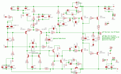
Since the VAS use some more current than the input pair transistors, maby, for the Dx Hr 1, there would be less variation of the current who goes to the input long pair transistors if we split the 135 ohm positive rail resistor in two, one 60 ohm before the 2k2 ohm Vas resistor plus a 100 uf capacitor from rail to ground , and one 75 ohm after that Vas 2k2 ohm resistor, (same for the Dx standard but we split the 82 ohm in two parts, 35-47 ohm ) I made an image of that for the Dx Hr 1 .
Theoricaly the Vas will have a bit more current with those split resistors and maby would give some more bass and faster sound.
Well... is a good or bad ideas ?
Thank
Bye
Gaetan
Just an ideas, not to ad modifications.
I like the simplicity of the Dx standard and Dx Hr 1, as usual I'm currious, so here's an ideas who keep those Dx simples and may have some possibles advantages without using a rail regulator for the LPT and VAS.
Since the VAS use some more current than the input pair transistors, maby, for the Dx Hr 1, there would be less variation of the current who goes to the input long pair transistors if we split the 135 ohm positive rail resistor in two, one 60 ohm before the 2k2 ohm Vas resistor plus a 100 uf capacitor from rail to ground , and one 75 ohm after that Vas 2k2 ohm resistor, (same for the Dx standard but we split the 82 ohm in two parts, 35-47 ohm ) I made an image of that for the Dx Hr 1 .
Theoricaly the Vas will have a bit more current with those split resistors and maby would give some more bass and faster sound.
Well... is a good or bad ideas ?
Thank
Bye
Gaetan
Attachments
![the high resolution dx[1]vas and lpt.jpg](/community/data/attachments/101/101399-744784e43fff8396dc2398cd1cb5361b.jpg)
The idea is fine, i have also tried into the old Ximple amplifier
But oscilated..... maybe because i was using those splitted resistances into the negative rail too.
You can try, maybe you will have better results...why not?
The positive rail resistance is smaller in value compared to the negative rail..... two ideas were used, the first one have a small reduction of voltage over those rail resistances; the second one had increase reduction of voltage.
Second idea sounded better but lost power, and this into the Standard Dx amplifier..... into the High Resolution II the rail electronic regulators made enormous difference.... advantages in sound quality...and this is very clear and easy to check.
Of course, the best idea will be double supply voltages... a bigger voltage to the input, also stabilized and well filtered, 5 volts more than the output voltage.... this will produce the better results as i could listen here once....but.... represents more parts, independent rectifiers and filters and complicates to constructors...they will need a double voltage output transformer...or worst, to use two transformers.
There are nice solutions, but sometimes they are more difficult to diy people to construct.... so..... waste of time to make something and publish, in such a way so complicated that no one will construct.... more than half the pleasure is to share, to see people constructing, having fun, being happy as a result your work and ideas..... the use of this idea will be waste of time, i think no one will construct.
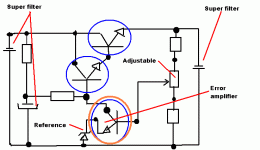
Even better is to use a higher voltage supply...let's say, plus 60 and negative 60, and them produce two different voltage regulators, one of them, a big power regulator, a lot of transistors and error amplifier, into the power regulator output enormous condensers...not only into the output (that will go to the power audio amplifier) but also into the input.... enormous power reserve..... those supplies you can have 100 or 200 amperes during small time shorts!... and a smaller voltage regulator (symetrical of course) to the input stages.....but even sounding better, this will turn construction more difficult, cost will increase and again, no one will construct...so...another waste of time.
Your Radford Gaetan, is not using filter condensers into the Higher voltage output, not good filtering...all your filter is electronic and the condenser is after the series regulator transistors.... not a very good, or perfect idea...but they had to do that, or the amplifier cost would rise too much, enormous condensers (those ancient days) would use enormous space inside the unit.... even not a perfect decision, but very reasonable, was taken...let to the voltage regulator the hard work to filter that pulsing DC that will enter the stabilizer, and let's believe the output condenser will complete the hard work.
I am happy to listen you once more.... and please, try your idea into real circuit and tell me and folks your results.
Into the Dx standard, the use of 2K resistances into the differential colectors and the use of the High Resolution VAS will produce a better sound...if you decise to substitute those colector resistances by a mirror, using two transistors, the sonics will not be better (my subjective, personal opinion, but different from the forum majority of folks ideas) but will be more precise...many folks will love that sonics.
The rail electronic regulators can be substituted by big condensers into the input...big rail filters will do the job too... sound quality is not too much different...we have to listen many times to perceive those differences (quality)..they are small, but goes to the electronic rail stabilizer.
You can see the sketch image... each rail, at least three transistors to power amplifier...and to the input more parts...this complicates, increase costs, result better sound..but not a very good idea to DIY, as people goes more easy to simple things.
regards,
Carlos
But oscilated..... maybe because i was using those splitted resistances into the negative rail too.
You can try, maybe you will have better results...why not?
The positive rail resistance is smaller in value compared to the negative rail..... two ideas were used, the first one have a small reduction of voltage over those rail resistances; the second one had increase reduction of voltage.
Second idea sounded better but lost power, and this into the Standard Dx amplifier..... into the High Resolution II the rail electronic regulators made enormous difference.... advantages in sound quality...and this is very clear and easy to check.
Of course, the best idea will be double supply voltages... a bigger voltage to the input, also stabilized and well filtered, 5 volts more than the output voltage.... this will produce the better results as i could listen here once....but.... represents more parts, independent rectifiers and filters and complicates to constructors...they will need a double voltage output transformer...or worst, to use two transformers.
There are nice solutions, but sometimes they are more difficult to diy people to construct.... so..... waste of time to make something and publish, in such a way so complicated that no one will construct.... more than half the pleasure is to share, to see people constructing, having fun, being happy as a result your work and ideas..... the use of this idea will be waste of time, i think no one will construct.
Even better is to use a higher voltage supply...let's say, plus 60 and negative 60, and them produce two different voltage regulators, one of them, a big power regulator, a lot of transistors and error amplifier, into the power regulator output enormous condensers...not only into the output (that will go to the power audio amplifier) but also into the input.... enormous power reserve..... those supplies you can have 100 or 200 amperes during small time shorts!... and a smaller voltage regulator (symetrical of course) to the input stages.....but even sounding better, this will turn construction more difficult, cost will increase and again, no one will construct...so...another waste of time.
Your Radford Gaetan, is not using filter condensers into the Higher voltage output, not good filtering...all your filter is electronic and the condenser is after the series regulator transistors.... not a very good, or perfect idea...but they had to do that, or the amplifier cost would rise too much, enormous condensers (those ancient days) would use enormous space inside the unit.... even not a perfect decision, but very reasonable, was taken...let to the voltage regulator the hard work to filter that pulsing DC that will enter the stabilizer, and let's believe the output condenser will complete the hard work.
I am happy to listen you once more.... and please, try your idea into real circuit and tell me and folks your results.
Into the Dx standard, the use of 2K resistances into the differential colectors and the use of the High Resolution VAS will produce a better sound...if you decise to substitute those colector resistances by a mirror, using two transistors, the sonics will not be better (my subjective, personal opinion, but different from the forum majority of folks ideas) but will be more precise...many folks will love that sonics.
The rail electronic regulators can be substituted by big condensers into the input...big rail filters will do the job too... sound quality is not too much different...we have to listen many times to perceive those differences (quality)..they are small, but goes to the electronic rail stabilizer.
You can see the sketch image... each rail, at least three transistors to power amplifier...and to the input more parts...this complicates, increase costs, result better sound..but not a very good idea to DIY, as people goes more easy to simple things.
regards,
Carlos
Attachments
Hi Geatan,
With a decent capcitor to the bootstrap, say 220uF instead of 47uF, the top bootstrap resistor should go straight to the +ve supply rail and not need any dropper with smoothing !
If you put additional C into the tail resistor adjustment pair as in your drawing, you will fractionally imbalance the differential pair.
The best place to connect additional C is at the Zener, and this combined with the 2k2 going to the rail means that the the top rail dropper can be linked out, also no advantage would then be gained from implementing a positive rail regulator.
Cheers ........... Graham.
Hi Carlos,
Presumably you are thinking about my comment relating to the 47uF capacitor, where I suggested 220uF.
47uF would be fine with a regulated +ve rail, but if you use 220uF it need not be regulated.
This is because the higher value capacitor will hold the bias/VAS current more constant through momentary bass peaks/psu dips.
No difference will be audible during normal listening, but the output stage will be more stable when running loudly.
An amplifier will make a loudspeaker cone 'breathe' if its DC bias conditions are not stable into the subsonic range.
Your rail regulators do this, but the simple DX does not have them.
I ended up simulating all of my proposed circuits by grounding its input and placing the source in series with each PSU source. This demonstrates the output variation response with PSU rail modulation at various frequencies.
(Quick Graham - RUN - where did you put that flameproof suit ?)
Cheers ............ Graham.
Hello
Carlos
If you did try it and have oscillations, I will not try it.
Ading a regulator are nice but and it would be no more the simplicity of Dx standard or Hr 1, and for the LTP collector resistance, I will keep them, it's a more simple sollution. I love simple circuit.
I'm surprise that Radford use a regulator because of the big size of capacitor, but it was 30 years ago and it was old tech parts I presume.
Graham
Your ideas of a bigger boot-strap capacitor are so simple, a kind of bigger reservoir cap.
Thank to both of you, I did learn few new knowledge today.
Gaetan
Graham Maynard said:Hi Carlos,
Presumably you are thinking about my comment relating to the 47uF capacitor, where I suggested 220uF.
47uF would be fine with a regulated +ve rail, but if you use 220uF it need not be regulated.
This is because the higher value capacitor will hold the bias/VAS current more constant through momentary bass peaks/psu dips.
No difference will be audible during normal listening, but the output stage will be more stable when running loudly.
Cheers ............ Graham.
Hello Graham
Is that mean that I can use even a bigger than 220 uf capacitor and it would give a better result for bias/VAS current during bass peaks/psu dips ?
I don't mind about the physical size of the capacitor, if bigger cap are better I will put big one.
Thank
Gaetan
Hi Gaetan,
Carlos has about 8mA VAS and two 2k2 resistors, so 220uF is probably fine. If the value of the upper bootstrap resistor is reduced, then a higher value bootstrap capacitor could be fitted to maintain LF stability.
220uF is probably all that would fit on the DX PCB.
Cheers ........... Graham.
Carlos has about 8mA VAS and two 2k2 resistors, so 220uF is probably fine. If the value of the upper bootstrap resistor is reduced, then a higher value bootstrap capacitor could be fitted to maintain LF stability.
220uF is probably all that would fit on the DX PCB.
Cheers ........... Graham.
Graham Maynard said:Hi Gaetan,
Carlos has about 8mA VAS and two 2k2 resistors, so 220uF is probably fine. If the value of the upper bootstrap resistor is reduced, then a higher value bootstrap capacitor could be fitted to maintain LF stability.
220uF is probably all that would fit on the DX PCB.
Cheers ........... Graham.
Hello
Ok... the size of the cap are inversely proportional to the upper bootstrap resistor value ?
What would be the result of a bootstrap capacitor who would have a to big size in uf ?
Gaetan
Sorry to interrupt...
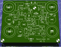
Just want to get more of the DIY details out there
Here is the silkscreen
D1/D4 & D6/D7 can be 1 or 2 zeners in series... I ordered 2 x 16V zeners for mine, as I only have a 35V supply.. obviously if you use only 1 zener, you need to bridge the other one...
Just want to get more of the DIY details out there
Here is the silkscreen
D1/D4 & D6/D7 can be 1 or 2 zeners in series... I ordered 2 x 16V zeners for mine, as I only have a 35V supply.. obviously if you use only 1 zener, you need to bridge the other one...
Attachments
Hi Gaetan,
Inverse relationship ? sort of ~YES.
Additionally, the upper bootstrap resistor is a separate AF load for the output stage via the bootstrap capacitor, which makes the upper resistor dissipate (max output V^2/R) plus (resistorV x vasI).
Thus a 1k upper resistor with 3k lower resistor and 40V rails will dissipate approx 700mW due to full output sine across it, plus 100mW due to VAS current, which equals 800mW.
(There will however be twice the AF induced dissipation with maximum square wave output, giving a total of 1.4W.)
The 1k resistor rating should not need to be more than 600mW for home audio duties, but would best be 1W for PA, and 2W for power driving purposes.
Capacitor value ? Too big a value = unnecessary size and expense.
A high value can slow the build up of output stage current and thus eradicate power-up thump in some circuits.
Cheers ............. Graham.
that's nice to know.A high value can slow the build up of output stage current and thus eradicate power-up thump in some circuits.
especially since adding capacitors in many other locations achive the exact opposite effect.
Graham.
there are a number of resistors being fed by the bootstrap capacitor.
How do you calculate the effective resistor value to insert into the RC calculation?
I would want the RC of the boostrap to be bigger than the RC of the high pass filter at the input. Is this a reasonable target?
Hi Andrew,
Carlos' circuits can sound good with a 47uF bootstrap due to output stage gain and the NFB loop compensating for any weakness, though beyond linear operation there would be an increase in distortion at maximum output and at low frequencies.
The top bootstrap resistor is the main load, the other being less important due to output stage gain for as long as the output stage is able to behave reasonably linearly. Beyond this it is pointless to calculate because we wish to optimise only the linear performance.
In my (not simple) amplifiers I also parallel the bootstrap capacitor with lesser values, for we do not want reactive impedance in the bootstrap circuit.
Cheers ............ Graham.
Dx standard has not power on "thump"
In the early begining it had...but after the inclusion of the zener and small condensers into the input supply i had no more noises during power on and off.
The maximum i could hear is the spark into my supply switch, as this switch has not capacitor to "eat" sparks that happens there when you flip the switch into the highest voltage levels, or lowest voltage levels into the mains sinusoidal signal.
The bootstrapp condenser was decided into a try and error basis...i started with 10uf and i have listened...then i replace to 22uf...and then 33uf...and then 47uf...and upper, higher values did not made increasings in sound quality.... 47 was decided as optimized to that circuit.
Dear Gaetan.... try those things, will be good to you to perceive those differences.
regards,
Carlos
- Status
- Not open for further replies.
- Home
- Amplifiers
- Solid State
- Destroyer x Amplifier...Dx amp...my amplifier