ostry said:I have one question: does C10 has to be 220uF/70V??? as far as i remember it has been 220uF/16V
Hi ostry,
Your not going crazy, it was changed.
regards
The good technical solution is to use high voltage condenser there.
Because if you have some damage in the amplifier, a short into one of the output transistors or other defect that increase the output line voltage, beeing 16 volts that condenser insulating voltage... you will have another component to replace...not only the burned transistor but also that 16 volts condenser that will not hold the voltage.
But using normally, you will never have 16 volts there...so, working normally the 16 volts condenser can work fine....but will be another burned part if your amplifier was subjected to a non normal operation.
By the way....use fuses into the rails and also fuse into the speaker output.... problems with the amplifier can send the supply voltage to the output and burn your speaker....better not to trust in your rail fuses only...install also a speaker fuse!
This condenser, beeing 35 volts is more safe.....70 volts or more is the safest solution, but the unit is big and ugly too..... deciding by the tiny pretty 220/16 volts, remember if you have burned transistors one day, to replace this 16 volts condenser too..
During normal operation, not only AC, but also DC, there in the positive lead of this 220uf condenser is very low.
In my circuits, my home units, as i know the small condenser is there, i am using 16 volts.... if something happens, i will be much more frustrated to replace the expensive output, this condenser replacement seems nothing related money.... and, after all...we do not go burning amplifiers so often.
regards,
Carlos
Lol Carlos, I changed the bias PCB for both channels to change to 1k multiturn trimpots... followed the instructions and pictures on Greg's pages.
But I will wire up the other channel in the morning to see if it does the same... because the 2 multiplier boards are the same now...
But I will wire up the other channel in the morning to see if it does the same... because the 2 multiplier boards are the same now...
nope, I have not yet tested the channel that worked before... but I did change its VBE multiplier, as the 1 turn put I had was very hard to set.
I'm busy makeing a picture of where to measure, which I will print, and then sit and complete the values on shorthly....
Will send you a copy for Greg's site...
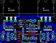
The bottom left arrows look wrong... the first arrow should be -33.7V
I'm busy makeing a picture of where to measure, which I will print, and then sit and complete the values on shorthly....
Will send you a copy for Greg's site...
The bottom left arrows look wrong... the first arrow should be -33.7V
Hi Nordic,
Okay I could not tell the difference between the 8 and a 0 with a line through it on post#2378 on my monitor.
I read R19 as 100 ohms !
So I will modify my question, is R19 on your PCB only 18 ohms ?
If R19 is okay, are the TIP transistors Q4 and Q5 okay/correct ?
Cheers ........ Graham.
Okay I could not tell the difference between the 8 and a 0 with a line through it on post#2378 on my monitor.
I read R19 as 100 ohms !
So I will modify my question, is R19 on your PCB only 18 ohms ?
If R19 is okay, are the TIP transistors Q4 and Q5 okay/correct ?
Cheers ........ Graham.

nope its a big 180R, voltage over it is vanishingly small... something like 0.4mv.
Will investigate anything you guys can point out in the morning... at the moment I asuspect an open circuit somewhere on the vbe board.. if carlos's description was accurately received relateing to the impendance xtremes.
Tips are both brand new... tip42, was expensive one from RS components... as I did not trust/understand the high Hfe at low loads.
In the past, Dx amplifier used resistance and trimpot to adjust the bias
They were VR2 and R14.... of course those components have to be removed when you will use the VBE multiplier.
If you forget those ones there, you will never reach a good bias level to all transistors....
But i think you did not made that mistake dear Nordic.
In the site, over the board image is writen:
"VR12 and R14 are obsolete"
And they are marked in red in the board's image to call people attention.
So folks,do not use them....remove them....they were substituted by the VBE multiplier circuit.
The home page, were you can have all needed informs about Dx amplifier is:
http://users.tpg.com.au/users/gerskine/dxamp/
Please, make us a visit, we will happy to see you there.
regards,
Carlos
Attachments
Graham Maynard said:Don't know how to delete completely.
Hi Graham, hahaha,

The PCB has been changed but Carlos didn't like "the direction I was going in" so the GE20070416 version is the final "published" version.
regards
>>> Post #2394
quote:
Originally posted by Graham Maynard
Don't know how to delete completely.
Hi Graham, hahaha, <<<
Hi Greg,
Bloomin computers.
One post disappeared, then the next appeared twice even though diyAudio is not supposed to accept 2 posts within one minute.
If we didn't laugh we'd all be bald.
Cheers ......... Graham.
Hi Nordic.
Arghh.
I never power up without cleaning and looking for tiny strings or blobs of solder which can land between tracks from a nearby joint.
Can I suggest you buy a pair of cheap 4 dioptre spectacles specially for checking pcbs.
I clean with methylated spirits and an old toothbrush, then check with spectacles, or magnifying lenses if the pcb has very finely spaced tracks.
Cheers .......... Graham.
Methylated Spirits....nice that name...is this Alcohol?
That evaporating liquid.... clear white colour, transparent and translucid.... that one made with fermented corn, or sugar cane... than destyled... something that remember alcoholic beverage?
Nice name.... more than nice...beautifull.
Ahahahha.... you are excelent with the English Language Graham.
I was thinking about the English people class related to speach:
- "Why this poor man is layed down in the street, with that dirty dog leaking his face?"
- I bad your pardon sir, but it seems excess of ingestion of Methylated Spirits!"
Ahahahahha...fine...not drunk!...excess of Methylated!
nice...very nice.
regards,
Carlos
Re Dx Turbo Version
Hi Carlos....how are you doing?????
I completed my schematic.. Please check all the resistor and capacitor values? Is P1 and P2 ok??? Is R31 1W enough???? please let me know. I want to start with the PCB Layout. Is all the transistors ok???? What about the output coil.......Is is not needed?????? Should I out a fuse to the speaker????
Thanks
macd
Attachments
- Status
- Not open for further replies.
- Home
- Amplifiers
- Solid State
- Destroyer x Amplifier...Dx amp...my amplifier