My first attempt at desoldering components. When desoldering some resistors/diodes or whatever they were I pulled out the little round silver ring (see the only brown hole in the attached pic), do in need to try and put it back or just solder in the new resistor?
Attachments
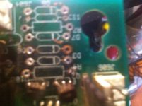
This looks much like a through hole eyelet in a double sided board bridging upper layer to bottom layer.
Push it back if able and confirm continuity with your DMM between points it intermediates.
Use solder wick and/or de-soldering pump gently. Work shortly with the iron and don't apply pressure to the pads in general, don't use it as a screwdriver somehow.
In (most possible) case it ain't fixable anymore, use the new component's leg and extend it to the nearest pad it used to be connected through that eyelet and associated pcb trace.
This looks much like a through hole eyelet in a double sided board bridging upper layer to bottom layer.
Push it back if able and confirm continuity with your DMM between points it intermediates.
Use solder wick and/or de-soldering pump gently. Work shortly with the iron and don't apply pressure to the pads in general, don't use it as a screwdriver somehow.
In (most possible) case it ain't fixable anymore, use the new component's leg and extend it to the nearest pad it used to be connected through that eyelet and associated pcb trace.
Thanks so much, believe eyelet is the term I was looking forand it probably is a double sided board, it comes from a williams pinball machine circa 1993ish.
So I think you are saying it probably intermediates points on both the top and bottom of the board and the connecting traces. so do i use my DMM to check continuity of the connecting traces further down the traces as in the next available point the trace can be contacted/checked with DMM lead. dumb question- but i assume the eyelet was all the way through from top to bottom of board and was an intermediary to every trace going to that hole?
It depends. Some have enough ring area of trace around them to only break the top to bottom connection if at a nodal position, some other times the trace is thin. There are pads that could be shiny but two dimensional only. The picture does not help but its easy for you to decide if simple shiny pads or plated through links. In any case the meter in continuity mode is your friend so to restore any connectivity damages. It will be a bodge to look at but working again is the main goal.
I still find desoldering components a swine to do. When I was working in a commercial electronics workshop we had a decent electric desoldering station which had a nozzle which heated the joint. When it melted you just pulled the trigger and an electric pump sucked out the molten solder from the joint, a great device which sadly I cant justify buying for infrequent home diy use.
That appears to just be a eyelet, if it is not connected to a track on the top, no damage done but the picture is not clear enough to be certain. If the track is damaged, just bridge the damaged area with a short length of thin solid core wire.
That appears to just be a eyelet, if it is not connected to a track on the top, no damage done but the picture is not clear enough to be certain. If the track is damaged, just bridge the damaged area with a short length of thin solid core wire.
Last edited:
There are some cheaper Chinese models maybe suitable for infrequent use on offer now, but don't expect warm up time, construction quality, reliability and ease of say Hakko desoldering station level. Still they get the job done if you are not a tools perfectionist.
Cheers Salas, I'll have a look on ebay later to see what's on offer. It's not something I need very often but could be handy to have.
See to get spares for it lest you should need some in the future and will be hard to track. There are some expendables in the collection chamber. O rings, sucked solder certain alloy retention coils and such.
I'll look into it mate, it'll probably have to wait until after new year now anyway - spend fest is almost upon us. The years seem to pass so quickly now it's bewildering.
Thanks guys, I believe its gonna be ok. When I hold the board up to the light I can see only one thick trace and it is connected at the bottom of the hole in question and still shows continuity. I think I just pulled of the top half of the eyelet and looks like everything will be fine when I solder in the new resistor/diode.
bTW I bought the FX--888D Hakko and the build quality is better than I expected.
bTW I bought the FX--888D Hakko and the build quality is better than I expected.
I use a solder wick for SMD pads.
For through hole I use a solder sucker. However this must be done with great care or the suction will lift off the pads. I hold mine at a slight angle so the pad doesn't get full suction.
For through hole I use a solder sucker. However this must be done with great care or the suction will lift off the pads. I hold mine at a slight angle so the pad doesn't get full suction.
I never had much luck desoldering SMD's. I usually just snip the legs if it's a chip but SMD resistors & capacitors can be a problem to remove without damage to the pads. Best way I found was to use two soldering irons (one on each end) and just flick the component off.
Thanks guys, I believe its gonna be ok. When I hold the board up to the light I can see only one thick trace and it is connected at the bottom of the hole in question and still shows continuity. I think I just pulled of the top half of the eyelet and looks like everything will be fine when I solder in the new resistor/diode.
bTW I bought the FX--888D Hakko and the build quality is better than I expected.
Good news 🙂
My first attempt at desoldering components. When desoldering some resistors/diodes or whatever they were I pulled out the little round silver ring (see the only brown hole in the attached pic), do in need to try and put it back or just solder in the new resistor?
You lifted a pad and partially ruined the board. When removing parts it causes the least damage if you cut the leads off first.
Your biggest enemy is a poor soldering iron. Insufficient heat won't melt and release quickly enough and too much will damage the bond of the copper to the board substrate.
Get the best soldering iron you can afford and then spend a little more.
I'm on record as using Metcals which are VERY expensive new but can be found on eBay ( all the ones I bought for me and my employers were eBay ). If you can't solder using a Metcal, you need to take up knitting instead.
G²
I use a solder wick for SMD pads.
For through hole I use a solder sucker. However this must be done with great care or the suction will lift off the pads. I hold mine at a slight angle so the pad doesn't get full suction.
I have a desoldering tool with a bulb that I bought from radio shack that I use for thru hole work. I avoid SMD anything as much as I can.
This RS tool works very well. The tip is a small tube, with the hole of the tube leading to the bulb. The tip heats up like a soldering iron. You place the tip over the lead of the component on top of the solder blob while you hold the bulb compressed. When the solder melts, you release the bulb and the liquid solder is sucked out and into the bulb where it cools on contact.
I have desoldered hundreds of joints with this tool and love it. It has a replaceable tip. I highly reccommend it, not typically something I say about RS stuff...
I was hoping I didn't ruin the board as when I use my DMM on the only trace I can see going to this through hole shows continuity, is there something I probably can't see that I ruined.?You lifted a pad and partially ruined the board. When removing parts it causes the least damage if you cut the leads off first.
Your biggest enemy is a poor soldering iron. Insufficient heat won't melt and release quickly enough and too much will damage the bond of the copper to the board substrate.
Get the best soldering iron you can afford and then spend a little more.
I'm on record as using Metcals which are VERY expensive new but can be found on eBay ( all the ones I bought for me and my employers were eBay ). If you can't solder using a Metcal, you need to take up knitting instead.
G²
I also lifted 3of the traces when removing transistors, guess I'm gonna have tread up on "stitching".
I have a new Hakko fx888d set at 750F and I am using solder wick,on some through holes it seems like I have to leave the iron on the blob/wick too long to clean the hole, like can it take as much as 25 seconds if the iron is on top of the wick?
I was hoping I didn't ruin the board as when I use my DMM on the only trace I can see going to this through hole shows continuity, is there something I probably can't see that I ruined.?
I also lifted 3of the traces when removing transistors, guess I'm gonna have tread up on "stitching".
I have a new Hakko fx888d set at 750F and I am using solder wick,on some through holes it seems like I have to leave the iron on the blob/wick too long to clean the hole, like can it take as much as 25 seconds if the iron is on top of the wick?
If it still has continuity it's more of a cosmetic problem but it's like auto body repair. If you can tell it's been worked on it's bad. Keep in mind you'll never get that Sony matte look - not that I want it.
The most time I ever have to spend clearing a hole is 10 seconds with the typical being 2-3. I use the old Edsyn Soldapullt which has been around since the dinosaurs. I have seen pads get 'vacuumed' up but it was either a really crappy board or damaged from excessive heat.
I use solder wick for a little clean up but it isn't nearly as effective as the sucker tool for clearing holes. The Metcal bent conical tip #26 is excellent for clearing plated through holes - better than any other I've tried.
The problem with most irons is the actual tip temperature is all over the place because the heater and temp sensors aren't at the tip but up the cylinder a ways so even though the sensor may be 700 the actual tip my be far cooler - and you don't know. The Metcal heater is also the sensor and is very near to the actual tip. Dunk a Metcal in water and it's melting solder again in a few seconds.
I've never used a Haako so I have no opinion but I doubt it's better than the Metcal. Prior to Metcals I was using the old Weller Magnastats which are only OK.
G²
Last edited:
Some folks don't realise that a dry soldering iron tip takes ages to transfer enough heat into the joint to melt the solder. Easily enough time to damage the board or component.
I always tin the irons tip with a smallish blob of solder first, then apply it to the joint, it then melts in a second or two at most because it transfers the heat almost instantly.
I always tin the irons tip with a smallish blob of solder first, then apply it to the joint, it then melts in a second or two at most because it transfers the heat almost instantly.
Some folks don't realise that a dry soldering iron tip takes ages to transfer enough heat into the joint to melt the solder. Easily enough time to damage the board or component.
I always tin the irons tip with a smallish blob of solder first, then apply it to the joint, it then melts in a second or two at most because it transfers the heat almost instantly.
The board looks horrible so I will do continuity checks on all points before and after I solder in the new components.
During desoldering, I lifted 3 traces, I don't think any are broken except where they attach to the eyelet, the lifted part of the trace Is about 2 inches on one, one inch on the second and the third is lifted about 1/64 inch.
How to fix?
Solder in the new component and try and position the lifted trace where it gets reattached/ soldered at the same time? Then reglue the trace back in its original trace line by applying some sort of glue. Hopefully just glue on top? What type glue?
Or
Forget all that and clip the lifted traces and use jumper wires? I presume the jumpers would need to be thin copper. Stranded or solid matter?
This is the high power voltage section of a dot matrix display driver circuit board on a 1993ish pinball machine.
Also concerning my earlier post on it taking 25 seconds to clean out a hole using wick. I think I had changed a setting on my unit resulting in a 750F reading on the display when the actual tip temp was only 550F.
Thanks for listening and more importantly, thanks for your comments!
Last edited:
30 gauge kynar wire wrap wire works well for most repairs. I had to use individual strands of wire about the size of hair to repair some 1/2 mm traces. The damage was not from the rework but from acid leaking from bad 'lytics. That can get to be VERY tedious.
A lot of damage comes from poor technique and lack of experience. I hope you're learning from the problems and living by Stratus46's motto. Always make NEW mistakes.
G²
A lot of damage comes from poor technique and lack of experience. I hope you're learning from the problems and living by Stratus46's motto. Always make NEW mistakes.
G²
- Status
- Not open for further replies.
- Home
- Design & Build
- Parts
- desoldering ?