We get the Peerless 830870 into the 30s in an ML-TL.
That's a good recommendation Dave, I have this available from local online shops too. The front shape will help with a narrow box. I bought the 4" coax to test. They will also be tested in my car sail area to replace the JL tweeters currently there. I blew the woofers in the doors, that system is set for an upgrade once the studio is setup
Last edited by a moderator:
Thanks, my gaff was not realizing the unit was an inch not cm -- line length ~ 90".That is a tapered TL simulation with variable stuffing at strategically placed locations to extend the bass rolloff and smooth the mid bass resonances. The impedance plot of a bass reflex and TL can look very similar. They are both vented and have a double peak with a saddle at the cabinet Fs. The TL has the resonance frequency based on 1/4 wave theory, whereas the BR is based on a Helmholtz resonator volume with a vent.
Still perplexed: Just below (to the left of) the QW resonance frequency but above the stuffed-line-induced phase-delay vector-sum break-even point (6*line-length waves at the effective speed of sound, so <25hz), I would have thought the driver and port output are net additive (unlike BR below Helmholtz). Can the sim display driver and port output phase curves? I think it would be enlightening at least to me!
Yes, they're additive because of the Mass of air coupled to the cone movement and...
I think I realized the significance of some green Curves I used to see in Many graphs (Sims) showed by Bjorno, R.i.p. he was very Active in the TL Camp.
Those Curves that looked like an oscillation and showed big dips of Many dB were the Total phase, so this means big nulls or reinforcent at certain frequencies. The sources are the speaker driver and the terminus, so the interference phenomenon happens. Same as phase tracking at XO frequency between two drivers
Helmholstz functions as the pressure outside the box Is counterfeited by the pression inside, the duct output Is in phase for a large interval which/why/where/Who!
Ok lesson finished, this Is what I know...
Wanna talk About cone movement coupled to a Mass of air?
Greets!However, I am still not understanding your explanation
In general, had to stop using PMs a long time ago now on all forums as way too many were trying to take way too much advantage of it/me.
Regardless, ATM can't come up with anything better short of someone else trying and/or you 'working through' Keele's T/S horn paper where I learned the T/S math behind what I understood from earlier learning about all manner of electric motor, solenoid, etc., design theory, most of which I've now long since forgotten, AKA 'use it or lose it'.

Hi Greg,
After thinking about it more, I believe that my misunderstanding was due to semantics. I understood the term "trade" as to give (part of) something in exchange for (part of) something another. thus thinking that when designing, e.g., a closed enclosure, one can exchange lower bandwidth for greater sensitivuty. But, I do not that this is what you meant/
Kindest regards,
M
Understood.In general, had to stop using PMs a long time ago now on all forums as way too many were trying to take way too much advantage of it/me.
After thinking about it more, I believe that my misunderstanding was due to semantics. I understood the term "trade" as to give (part of) something in exchange for (part of) something another. thus thinking that when designing, e.g., a closed enclosure, one can exchange lower bandwidth for greater sensitivuty. But, I do not that this is what you meant/
Kindest regards,
M
Right, we can have 'x' BW @ 'y' SPL or 'trade'/'exchange' less/more BW for less/more 'y' SPL, but not both at the same time, i.e. 'can't have your cake and eat it too', and as we 'slide' this 'X' BW backwards in time/going lower in frequency, so goes efficiency in lockstep if we don't increasingly narrow up its BW to compensate.
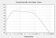
Well, with the closed box we can trade efficiency for gain BW by increasing the driver's Qts with 8 ohms of added resistance (attached) with the downside of it being a lot (- 6+ dB/200 Hz mid band) just to gain the modest hump down low, i.e. not many 'free lunches' in audio reproduction design.

Well, with the closed box we can trade efficiency for gain BW by increasing the driver's Qts with 8 ohms of added resistance (attached) with the downside of it being a lot (- 6+ dB/200 Hz mid band) just to gain the modest hump down low, i.e. not many 'free lunches' in audio reproduction design.
Attachments
Guys, I need to set a tuning range for the jig. It will be tunable in any chosen steps. Lower limit can go around 30hz for a still desktop friendly footprint of just under 40 cm. What's a good upper limit? 70Hz? Keep in mind that the built cab height and width are fixed, cab depth is jig printed to the upper limit. Then slices are added to tune down to a lower frequency by increasing tunnel length. Think of a whole loaf of bread cut in half, then a bunch of sliced bread inserted in the cut to make the loaf wider. The jig uses hidden booker rods for final assembly and gluing and has a tunable dampening effect. There is a bit of my research and testing in there that I won't elaborate on, but sufficient to say that the jig and assembly system has a measurable and audible dampening control effect
Nowadays the THX 20 Hz Fb, 80, 120 Hz XO points are the norm, though if sticking with octave spreads, then 20/80, 30/120, etc..
GM
Thank you. I think I may have either a totally stupid question or an entirely valid one, is there still any point to making a TL for speakers that don't really do much in the 100hz and below area? Is there a point where a smaller sealed cab will be more than sufficient?
Thank you. I think I may have either a totally stupid question or an entirely valid one, is there still any point to making a TL for speakers that don't really do much in the 100hz and below area? Is there a point where a smaller sealed cab will be more than sufficient?
You're welcome!
Like most things, it depends on the needs of the app with a prime one being how wide a BW above the XO point and XO slope order, so to the first approximation the narrower the desired BW and/or the higher the XO slope, sealed is increasingly the better choice overall IME.
Like most things, it depends on the needs of the app with a prime one being how wide a BW above the XO point and XO slope order, so to the first approximation the narrower the desired BW and/or the higher the XO slope, sealed is increasingly the better choice overall IME.
Thank you man, really appreciate the time you take to answer things

- Home
- Loudspeakers
- Multi-Way
- Desktop TL template audio discussion