The Linkwitz-transform sounds really interesting. It could maybe correct the problems in the frequency response. But what I would like to know is, that does a high Q and poor control over the cone cause any problems that are not clearly visible on the frequency response? Can it cause a bad transient response, for example? And if so, doesn't the Linkwitz transform only correct the frequency response?
The Linkwitz transform circuit (or any other type of biquad designed to equalize the loudspeaker's response) will automatically also correct the transient response. There are two limitations:
1. As you don't know the loudspeaker's response exactly, you can never place the zeros of the Linkwitz transform exactly at the poles of the loudspeaker's transfer, and as a result, you are left with a small ringing with the original Q
2. When you mechanically excite the loudspeaker, for example by tapping on its cone, the resulting response will damp out with the original, uncorrected Q
If you had a Q of 100, I would worry about these things, but not with a Q of about 2. The transient response of your loudspeakers in a big closed box with a Linkwitz transform circuit will still be superior to that of an ESL-63, and I used to own ESL-63s and liked them very much.
By the way, another alternative is driving the loudspeakers from a negative resistance. It doesn't have the limitations of the Linkwitz transform circuit, but it aggravates distortion and compression effects due to voice coil heating.
So as someone posted earlier, using the Linkwitz transform with this driver would maybe need a pretty large box. The Vas of my driver is 33 litres, so the box would have to be about 100 litres. Could I use the kind of aperiodic, damped enclosure (with acoustically resistive material), with Linkwitz or some other similar EQ circuit? Or do they work only with closed enclosures? I would still prefer a smaller enclosure, wich would probably be possible with th damped design. However, if the sound quality is better, I could still do maybe 100 litres.
This sounds interesting too. However, I think that maybe the limitations of the Linkwitz transform are not too bad.
By the way, another alternative is driving the loudspeakers from a negative resistance. It doesn't have the limitations of the Linkwitz transform circuit, but it aggravates distortion and compression effects due to voice coil heating.
This sounds interesting too. However, I think that maybe the limitations of the Linkwitz transform are not too bad.
Last edited:
You can also use a smaller closed box, but then both the resonant frequency and the Q increase, theoretically by a factor of sqrt(2) when you use 1 Vas. Due to the higher Q, the slight ringing you get because the zeros of the Linkwitz transform are not exactly on top of the poles of the box needs more cycles to damp out, so I can't claim anymore that the transient response is better than an ESL-63.
I don't know much about damped enclosures, but I expect they should work fine with a Linkwitz transform circuit. Basically anything that behaves similar to a second-order minimum-phase high-pass from electric input to sound pressure output can be equalized, does a damped enclosure have an approximately second-order high-pass response like a closed box?
I don't know much about damped enclosures, but I expect they should work fine with a Linkwitz transform circuit. Basically anything that behaves similar to a second-order minimum-phase high-pass from electric input to sound pressure output can be equalized, does a damped enclosure have an approximately second-order high-pass response like a closed box?
Last edited:
Mattes:
Thank you for telling me about the FEMM. I will definately have to check it out.
Hi Olijo,
FEMM takes the guesswork out of motor design and is a great tool. The results may not be 100% correct, but with such a large airgap, measurement should be easy, a chinese gaussmeter with a small probe is less than 100 €.
Pure iron, by the way, is available here:
Pure iron | Pure Iron | Raw material | Forging | Angele Shop
in 60mm and 100mm round bars, OK, it´s not exactly cheap. Also here
Pure Iron - PURON Metals
but I have no idea of MOQ´s.
Other low carbon steels are relatively easy available.
All the best
Mattes
Thanks for the links. Often the biggest problem may be the minimum order quantity, and my lack of cutting tools. Everything would be easier, if I had all the tools to make iron parts with correct shape, and if I wouldn't live in a multi-storey block building.
However, I think that the material is probably not the biggest problem with the driver. I'm using Fe52/S355 steel, which should have magnetic saturation around 2 T and permeability somewhere around 1000. I'm not sure about it, but I think that could be enough when I use a super strong magnet. I should maybe try modeling it on FEMM to find out. It's also possible that the shape of the magnet structure is not optimal.
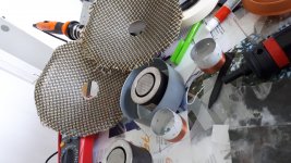
I'm using quite soft spiders (spiders and surrounds are the only non-DIY parts), and I wonder if that can also have some effect on the mechanical Q. Unfortunately, I don't have many photos of the building process (but I have some video that I will edit and publish later), I can still attach one photo that can maybe give some idea about how it looks. However, during the building process of the motor, I tested the system without attaching a cone yet, and at that time it felt like it was actually quite strong. Nevertheless, I have no reference to compare it to, maybe I just thought it was pretty strong.
I started making an aperiodic cabinet for the woofers. That could maybe damp the high Q-value enogh. I will post the results here when it's finished.
However, I think that the material is probably not the biggest problem with the driver. I'm using Fe52/S355 steel, which should have magnetic saturation around 2 T and permeability somewhere around 1000. I'm not sure about it, but I think that could be enough when I use a super strong magnet. I should maybe try modeling it on FEMM to find out. It's also possible that the shape of the magnet structure is not optimal.
I'm using quite soft spiders (spiders and surrounds are the only non-DIY parts), and I wonder if that can also have some effect on the mechanical Q. Unfortunately, I don't have many photos of the building process (but I have some video that I will edit and publish later), I can still attach one photo that can maybe give some idea about how it looks. However, during the building process of the motor, I tested the system without attaching a cone yet, and at that time it felt like it was actually quite strong. Nevertheless, I have no reference to compare it to, maybe I just thought it was pretty strong.
I started making an aperiodic cabinet for the woofers. That could maybe damp the high Q-value enogh. I will post the results here when it's finished.
Attachments
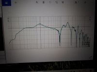
I made a spherical aperiodic enclosure for the woofer. Otherwise it seems ok, but there's some resonance between 100 and 200 Hz. The whole enclosure is stuffed with glass wool, and there is a 5cm diameter damped port in the back of the sphere. I don't know what causes the bump. I don't believe that it's caused by room modes, as I measured it from quite near of the speaker and the bump is quite wide. On the other hand, the cabinet is full off glass wool, so could the cabinet still resonate like that? Seems pretty weird.
I wonder if I could still tune it some way, like making the port larger or something, or adding mass to the cone (this would feel pretty stupid). Or if there is any passive analog EQs I could use for it. It doesn't sound horrible, but I wouldn't want to leave it like this.
Edit: I calculated the resonant frequency of a spherical helmholz resonator that size, and it should be somewhere 110 Hz, if the hole is 5cm. Maybe I should make a larger hole?
Attachments
Last edited:
Or should I make the hole smaller? I maybe uderstood it wrong. However, I i make it smaller, it will maybe be less efficient in damping and more like an air spring. If I make a bigger hole, the resonance shifts higher, but does the peak go higher or lower? Or should I just put more and more glass wool 😀
I don't know what causes the bump. I don't believe that it's caused by room modes, as I measured it from quite near of the speaker and the bump is quite wide.
The bump wasn't there post 18.
This indicates that the different enclosure (or test conditions) caused it.
Is the diaphragm on your driver conical (straight wall)?
If so, here is a link to another straight walled driver showing "nearfield measurements".
Wharfedale Super 8
That is the sort of response I think you would hope to see.
.
Note 1: your woofers seem to be low efficiency, about 80dB / 1 watt, based on sticking the numbers into this calculator:
HiFi Loudspeaker Design
Note 2: you can mock up enclosures and open baffles using cardboard. For extra strength, you can laminate a couple of layers of cardboard together using cheap wood glue + weights. The weights can simply be heavy books.
Last edited:
when I measured with REW, some strange comb filtering appeared in the response. That does not exist in the actual fr, but it is probably caused by something in my measurement setup.
Maybe it is caused by the big metal lip in front of the driver.
As an experiment:
- measure the driver as it is.
KEEP everything the same (driver and mic position and sound levels)
- add a strip of foam (e.g. window sealer) to the inside of that lip.
- measure again.
If the comb effect is softer, you know the lip is to blame.
I think it should be correctable with a Linkwitz transform circuit.
What does the impedance look like as a function of frequency?
What does the impedance look like as a function of frequency?
I think it should be correctable with a Linkwitz transform circuit.
What does the impedance look like as a function of frequency?
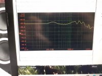
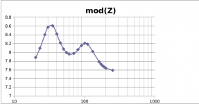
I made it to measured it today. However, I have not compensated the resistance of the cables etc. And also I'm not sure how accurate is it. But maybe this tells you something. The resonances seem to be at 30 Hz and 105 Hz.
Attachments
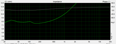
It looks like a very damped bass reflex box with an unusual tuning. If you give me a couple of days, I'll try to fit it to a simple LRC circuit and determine the zeros of its impedance, which should be the poles of the transfer from voltage to sound.
Don’t overlook common bubble wrap as a stuffing material as well, I usually wind up with a combination of materials.
Cool project as well!
Cool project as well!
Don't take what I'm about to write too seriously, as I have no idea if my fit is good enough.
Anyway, I used an Excel sheet and some manual tweaking to fit your impedance graph to an LRC circuit, then used a program called LINDA (LINear Dynamic circuit Analyzer) to extract the poles and zeros of its impedance. Theoretically the zeros of the impedance should be the poles of the transfer from voltage to sound, at least at low frequencies.
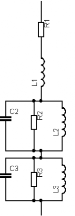
I used the circuit in the attachment and ended up with these values:
R1 7.4 ohm
L1 878.24 uH
L2 909.45 uH
R2 0.72 ohm
C2 2.526267 mF
L3 4.421944 mH
C3 5.304 mF
R3 1.17 ohm
The extracted zeros of the impedance are at (-93.875 +/- 184.766 j) rad/s and (-303.426 +/- 586.802 j) rad/s and an irrelevant real zero due to voice coil inductance (at -8342 rad/s).
Expressed in natural frequencies and Q factors, these are two resonances with a Q close to 1.1, one around 33 Hz and one around 105 Hz.
Assuming this is close enough to the truth, you can either
1. Use a Linkwitz transform circuit to extend the bass. When you convert the 105 Hz, Q ~= 1.1 resonance into 33 Hz, Q ~= 0.56, you end up with a 33 Hz fourth-order high-pass response that is somewhere in between Butterworth and Linkwitz-Riley,
or
2. Use a Linkwitz transform circuit to cut the bass. When you convert the 33 Hz, Q ~= 1.1 resonance into 105 Hz, Q ~= 0.56, you end up with a 105 Hz fourth-order high-pass response that is somewhere in between Butterworth and Linkwitz-Riley,
However, when I simulate the uncorrected response assuming poles at (-93.875 +/- 184.766 j) rad/s and (-303.426 +/- 586.802 j) rad/s and four zeros in the origin, I only get a peaking of 2.06 dB. That makes me wonder whether the fit and the assumption of lumped behaviour are really good enough.
Anyway, I used an Excel sheet and some manual tweaking to fit your impedance graph to an LRC circuit, then used a program called LINDA (LINear Dynamic circuit Analyzer) to extract the poles and zeros of its impedance. Theoretically the zeros of the impedance should be the poles of the transfer from voltage to sound, at least at low frequencies.
I used the circuit in the attachment and ended up with these values:
R1 7.4 ohm
L1 878.24 uH
L2 909.45 uH
R2 0.72 ohm
C2 2.526267 mF
L3 4.421944 mH
C3 5.304 mF
R3 1.17 ohm
The extracted zeros of the impedance are at (-93.875 +/- 184.766 j) rad/s and (-303.426 +/- 586.802 j) rad/s and an irrelevant real zero due to voice coil inductance (at -8342 rad/s).
Expressed in natural frequencies and Q factors, these are two resonances with a Q close to 1.1, one around 33 Hz and one around 105 Hz.
Assuming this is close enough to the truth, you can either
1. Use a Linkwitz transform circuit to extend the bass. When you convert the 105 Hz, Q ~= 1.1 resonance into 33 Hz, Q ~= 0.56, you end up with a 33 Hz fourth-order high-pass response that is somewhere in between Butterworth and Linkwitz-Riley,
or
2. Use a Linkwitz transform circuit to cut the bass. When you convert the 33 Hz, Q ~= 1.1 resonance into 105 Hz, Q ~= 0.56, you end up with a 105 Hz fourth-order high-pass response that is somewhere in between Butterworth and Linkwitz-Riley,
However, when I simulate the uncorrected response assuming poles at (-93.875 +/- 184.766 j) rad/s and (-303.426 +/- 586.802 j) rad/s and four zeros in the origin, I only get a peaking of 2.06 dB. That makes me wonder whether the fit and the assumption of lumped behaviour are really good enough.
Attachments
Last edited:
Thank you MarcelvdG for the calculations. It is really possible that the system is not so easily presented with lumped behaviour models, as it's quite unconventional design. I would gladly use some circuit like that, but I think 2dB reduction in the peak would still probably be too little.
What do you think about this Linkwitz-transform calculator?
HiFi Loudspeaker Design
I thought, that I could estimate the Q-values just by visually looking at the frequency response of the speaker, and the frequency response of the filter (maybe using the miniDSP LT excel-sheet as a tool for estimating the Q). However, I have no idea if that actually makes any sense. Also, too much bass boost could cause problems, as it increases the voice coil excursion. However, that won't be a big problem, if I high pass the system, leaving some room for a subwoofer.
It could also be that my assumption of four zeros in the origin is wrong. They are practically in the origin with a bass reflex box, but you deliberately add acoustic resistance, which may shift them to some negative real location.
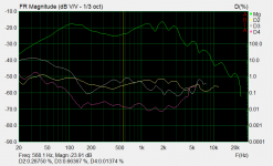
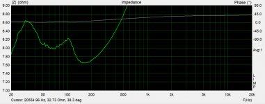
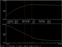
Attached are your measured graph and my simulated graph assuming four zeros in the origin. The simulated graph has a rad/s frequency scale, so all frequency values are 2 pi times larger than you would expect (peculiarity of the program I used). It's at -3.1 dB at 474.24 rad/s, so 75.48 Hz, and somewhere around -40 dB at 20 Hz. Your measurements only show a roll-off of about 20 dB at 20 Hz.
Attached are your measured graph and my simulated graph assuming four zeros in the origin. The simulated graph has a rad/s frequency scale, so all frequency values are 2 pi times larger than you would expect (peculiarity of the program I used). It's at -3.1 dB at 474.24 rad/s, so 75.48 Hz, and somewhere around -40 dB at 20 Hz. Your measurements only show a roll-off of about 20 dB at 20 Hz.
Attachments

Last edited:
What do you think about this Linkwitz-transform calculator?
HiFi Loudspeaker Design
Looks good, but I never used it.
I thought, that I could estimate the Q-values just by visually looking at the frequency response of the speaker, and the frequency response of the filter (maybe using the miniDSP LT excel-sheet as a tool for estimating the Q). However, I have no idea if that actually makes any sense. Also, too much bass boost could cause problems, as it increases the voice coil excursion. However, that won't be a big problem, if I high pass the system, leaving some room for a subwoofer.
That makes sense. You could use the corrected response as part of the crossover filter, that is, Linkwitz transform the pole pair around 105 Hz into a pole pair of your crossover.
- Home
- Loudspeakers
- Multi-Way
- Designing cabinets for high Qts DIY drivers