not necessarily.unclejed613 said:your compensation cap C9 goes from the VAS to the inverting input of the diff amp. shouldn't it go to the base of Q2?
The two stage feedback usually needs other compensation locations to work adequately but when done this way is reputedly better sounding than adding capacitance that must be modulated by the LTP.
Well, it does indeed sound very good! 🙂 Haven´t tried the IRF devices yet, so I can´t tell which will sound better but the Toshiba FETs surely have a good reputation and seem to be very robust.
We actually did a A/B test with another amp (descrete amp, traditional topology with bipolar output) and I think "our" amp sounded more clean in the treble range, but the biggest difference is the absolutely rock solid bass! Very powerful with good control.
We actually did a A/B test with another amp (descrete amp, traditional topology with bipolar output) and I think "our" amp sounded more clean in the treble range, but the biggest difference is the absolutely rock solid bass! Very powerful with good control.
Not a problem with this amp since it already has some temp compensation. But it doesn´t have any protection circuitry, so that´s another reason to stick to the Toshiba devices instead, and we already know they sound good.
Hi,
you can and should still use Zeners to limit the Vgs and down rate the Zener to achieve some measure of current limiting.
Many state (in my view erroneously) that FETs, both vertical and lateral, don't require VI limiting presumably due to the near absence of secondary breakdown.
But, do check the Zener and gate resistor dissipations if this limiting is ever triggered.
I chose the zener values to make sure they don´t trigger unless when something exceptional is happening. As far as I know, lateral FETs transconductance collapse at very high currents, and my hope was that this will be a sufficient protection by itself. The zeners are there to make sure maximum Vgs is not exceeded.
For the same reason, I want to avoid vertical FETs. Maybe I´m wrong about this.
Next week I will "terrorise" the amp with low impedance loads, connecting caps across the load etc. I want to find the point where it gets unstable. Hope the Toshiba devices will survive!
For the same reason, I want to avoid vertical FETs. Maybe I´m wrong about this.
Next week I will "terrorise" the amp with low impedance loads, connecting caps across the load etc. I want to find the point where it gets unstable. Hope the Toshiba devices will survive!
Yes lateral FETs tend to survive due to increased source resistance, decreased transconductance and ultimately the internal zeners or something starting to conduct like thyristors when the temperature gets high.
The Toshibas are not laterals though, they are of the vertical kind (look at the pinout), and will probably not survive this kind of treatment 🙂 Hafler used 10V zener clamps on the gates for Hitachi laterals and this was enough to make them pretty indestructible by overloading. I did a test earlier with a lateral fet on a minimal heatsink. 50V 10A power supply between D-S and then hitting it with 10V on the gate through 330 ohm resistors (the gate terminal will start drawing current when temperature gets high) and I did not manage to destroy it even with repeated attempts.
The Toshibas are not laterals though, they are of the vertical kind (look at the pinout), and will probably not survive this kind of treatment 🙂 Hafler used 10V zener clamps on the gates for Hitachi laterals and this was enough to make them pretty indestructible by overloading. I did a test earlier with a lateral fet on a minimal heatsink. 50V 10A power supply between D-S and then hitting it with 10V on the gate through 330 ohm resistors (the gate terminal will start drawing current when temperature gets high) and I did not manage to destroy it even with repeated attempts.
According to Mr Cordell these Toshibas are "most definately lateral". And I read somewhere in this forum that the negative temp coefficient begins at currents over 6.5 amps or something like that. So I do believe they will be kind of hard to kill.
Reducing the zener values could be in place either way, it depends on what top currents I can measure when overloading it next week. The plan is to go down to 1 ohm and bringing the amp to the clipping point with pulsed sinus. If everything looks ok, the next step will be to connect capacitors across the load. Somewhere it will become unstable. I did connect LEDs in series with the zeners so I can tell if they conduct.
Also interesting will be to see how it recovers from clipping.
🙂
The lateral fets have the zero tc point at about 100mA - a difference of almost 2 decades compared to 6 amps.
The Toshibas are most definetly not laterals (look at the pinout too) BUT this does not mean they would be bad for audio or anything.
They do have some advantages over the laterals, like giving you higher peak currents. Cordell has written a paper that explains that speakers may under some rare circumstances require 2-3 times the peak current you might expect. If you want to be able to supply that with laterals you will need to parallell transistors just to get the peak current as they won't let through as much current as you might expect when they are warm/hot.
You will have less rail drop and higher output power for the same supply voltage too due to higher transconductance and lower on resistance.
What kind of protection is it that you are after? If you want it to be short circuit proof and low-impedance contiuous sine proof you will probably need some kind of active protection. If you do not care about that and are only going to drive speakers with music then the Toshibas will be rugged enough if you use an appropriate number of pairs.
Interesting, we are still debating if these FETs are lateral or not. I have to correct myself, Bob did in fact say they are vertical! Some say it doesn´t matter since the temp coefficient is what is important. We already know the Toshiba´s are good for audio, they were developed for it. And does absolutely sound good.
What I´m after is simply making the amp robust enough to allow for occasional shorts, for example speaker wires lying on the floor when testing speakers. These tend to short sometimes, and it would be too bad if the amp can´t take that. Most often it happens with no signal, so I don´t think it would be a problem.
Not the main issue though, implementing some sort of linearising network around the output is what this amp would really benefit from.
what?Rikard Nilsson said:implementing some sort of linearising network around the output is what this amp would really benefit from.
Yes, as I originally tried, like the Cordell EC. Or sliding bias, or anything that might reduce the crossover distorsion.
I am trying to simplify the Cordell circuit, and if it works in the sim I will try for real later.
I am trying to simplify the Cordell circuit, and if it works in the sim I will try for real later.
Haven´t had the time to continue this amp development, but did some more simulation and are about to try it live.
I added cascode FET drivers, just for fun actually, and it seems to work well in simulation at least. Don´t have them at home, but will try for real later.
Before I do, do you guys have any suggestions? Especially better ways to stabilize this amp.
Thankful for your thought. By the way, my apologies for the messy schematics....
Some info: R34 adjusts the error correction balance, R32 is bias. R18 is the load.
🙂
http://www.autostock.se/download/?FILE_ID=Circuit 9 EC c.ms8
I ran your MultiSim. Worked right out of the box!
(only changed extension to .ms9 = multisim9 file)
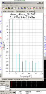
Nice FFT.
Output 22.5 Watt RMS into 3.9 Ohm .. with zobel+output inductor filters.
Not much higher order dist. Some little 2nd + 3rd only.
The upper -3 dB is at ~170 kHz
(only changed extension to .ms9 = multisim9 file)
Nice FFT.
Output 22.5 Watt RMS into 3.9 Ohm .. with zobel+output inductor filters.
Not much higher order dist. Some little 2nd + 3rd only.
The upper -3 dB is at ~170 kHz
Attachments
Thanks lineup!
You have a better simulator than i do! 🙂
This was better than I expected actually. Did you expericence any instability? I tried lowering the load resistance and introduce inductive and capacitive components until it became unstable. Seems to drive ok down to 1 ohm or less.
Didn´t manage to get a slew rate figure, but maybe you can see it easily?
Another thing, does the Multisim 9 allow adjusting values while simulating? Would be interesting to see if the error correction balance can be tweaked during simulation.
Rgs Rikard
I think you have most of my functions, too.
To check instability.
just run your function generator squarewave: 1 kHz (maybe 10 kHz)
while keeping the output level very low (maybe 0.2 - 1.0 Volt)
and the load light, say>= 8 Ohm
(Because instability will show where the Open Loop Gain is biggest, at high frequencies.
And if instable=oscillation or not 100% stable, your squarewave will show bad shape)
I did not see any instability, with the test values you had default.
And your zobel + output inductor probably helps with this.
Adjusting values while Run test.
There are several components, like potentiometers, you can adjust while running.
And your function generator output level.
There are also special components, current and voltage sources, that are adjustable, too.
Using different buttons at your keyboard.
Otherwise we can run several tests with different values, of course.
I do not know how to use all tests with MultiSim.
Like noise tests. I haven't figured out, yet.
We have EWB forums:
http://forums.ni.com/ni/
Forum: Circuit Design Suite, Multisim, Ultiboard
There is also this online course:
Like noise tests. I haven't figured out, yet.
We have EWB forums:
http://forums.ni.com/ni/
Forum: Circuit Design Suite, Multisim, Ultiboard
There is also this online course:
Introduction to Multisim Schematic Capture and SPICE Simulation
http://cnx.org/content/col10369/1.3/
Table of Contents
Introduction
*
Schematic Capture
*
Circuits
*
Simulation
*
Integrated Design and Academic Features
Thanks a lot! Will replace with a trimpot and see if the distorsion figures can be optimized. (eventhough I know they will probably behave completely different once I´ve built the thing.)
🙂
🙂
Here you can download MultiSim-8 User Guide ( 8.5 MB)
http://proton.ucting.udg.mx/tutorial/multisim/
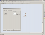
See my attachment.
Add component: BASIC-> BASIC_VIRTUAL -> POTENTIOMETER_VIRTUAL
Right Click -> Properties(Egenskaper)
-------------------
KEY: what keyboard button to use for pot.
key gives incresed value. To decrease SHIFT+key
INCREMENT: how much each step will increase, in %
10%, 5% steps, or even 0.01% etc.
RESISTANCE: the ohm value for pot
-------------------
Now you can can press correspoding key or shift+key
to change values of several potentiometers, while running your circuit
and having some test instruments at output (like Oscilloscope, Distortion Analyzer, Multimeter ...)
http://proton.ucting.udg.mx/tutorial/multisim/
See my attachment.
Add component: BASIC-> BASIC_VIRTUAL -> POTENTIOMETER_VIRTUAL
Right Click -> Properties(Egenskaper)
-------------------
KEY: what keyboard button to use for pot.
key gives incresed value. To decrease SHIFT+key
INCREMENT: how much each step will increase, in %
10%, 5% steps, or even 0.01% etc.
RESISTANCE: the ohm value for pot
-------------------
Now you can can press correspoding key or shift+key
to change values of several potentiometers, while running your circuit
and having some test instruments at output (like Oscilloscope, Distortion Analyzer, Multimeter ...)
Attachments
- Status
- Not open for further replies.
- Home
- Amplifiers
- Solid State
- Designing amp with 2SJ201/2SK1530