You should be able to "tune" a "trioded" Mosfet device (trioded = Drain Fdbk) by putting a source resistor Rs in series with the device source terminal. With high Rs, the device is near linear. With no Rs the device is square law. With Rs = 1/gm the device should be about half way between a square law device and a linear device. Ie, a 3/2 law device, like a tube. Of course gm will be halved around there with that Rs addition.
------------------------------------------------------------------------------------------------------------------
The real tube however still reigns supreme in a modified tube circuit that seems to be unknown:
You take a pentode and put in the resistors for Crazy Drive. (R1 from grid2 to grid1, 4K say. And R2 from grid1 to cathode, 4K say. Also try R2 from grid1 to Gnd or some - Bias V, may simplify biasing. ) Then we add UnSET to it. Which is resistive Schade Fdbk plus a P channel follower to drive the cathode. The resistive Schade would be a high value resistor from plate to grid2 in this case. (normally to grid1 for Unset) Say 100K from plate to grid2. And then a P channel follower goes under the cathode to drive it. With everything combined (some R value tweaking for the specific tube likely), you can get linear mode triode curves. Or a "Wire with Gain". Here is a curve trace: (been mentioned several times, but never gets any interest)

Here is Crazy Drive alone:

And here is UnSET alone:

------------------------------------------------------------------------------------------------------------------
The real tube however still reigns supreme in a modified tube circuit that seems to be unknown:
You take a pentode and put in the resistors for Crazy Drive. (R1 from grid2 to grid1, 4K say. And R2 from grid1 to cathode, 4K say. Also try R2 from grid1 to Gnd or some - Bias V, may simplify biasing. ) Then we add UnSET to it. Which is resistive Schade Fdbk plus a P channel follower to drive the cathode. The resistive Schade would be a high value resistor from plate to grid2 in this case. (normally to grid1 for Unset) Say 100K from plate to grid2. And then a P channel follower goes under the cathode to drive it. With everything combined (some R value tweaking for the specific tube likely), you can get linear mode triode curves. Or a "Wire with Gain". Here is a curve trace: (been mentioned several times, but never gets any interest)
Here is Crazy Drive alone:
And here is UnSET alone:
Last edited:

I've searched for that UnSET a couple times and never have seen schematics or an amplifier design using them. EDIT: Over in the tube lab forum I see, not sure if there's any other examples of people implementing it, I'd be curious.
I had messed around with Gary Pimm's HV cascoded mosfet amplifier stuff in the past but have had too many stability problems with current production mosfets.
I had messed around with Gary Pimm's HV cascoded mosfet amplifier stuff in the past but have had too many stability problems with current production mosfets.
Last edited:
The UnSET and related stuff is over on Tubelab's (George's) forum. The idea originated ( I think, at least for me ) from the realization that ordinary Resistive Schade Fdbk (resistor from plate to grid1, and the input current drive on grid1 ) has a flaw in it. The resulting grid1 voltage variation corrupts the Schade resistor Fdbk current. Resulting in cramped triode curves at the HV end. This can be fixed conveniently in two ways. A grounded gate P Channel Mosfet can be placed at the bottom end of the Shade Fdbk resistor to convert the N Fdbk to isolated current at the Drain end for grid1 (so un-affected by grid1 V variation there) OR one can just move the drive signal to the cathode instead, providing isolation. (with an R divider resistor added from grid1 to gnd )
That also requires a P channel Mosfet to drive the cathode, but in V follower fashion. The tube gm still determines cathode current, so tube authenticity is still preserved. This also has the effect of effectively increasing tube B+ when the cathode is pulled negative. So power output is increased (sum of tube power plus driver power ) Clearly of some interest to George. 🙂 The lowish screen V for TV Sweep tubes can be accommodated as well, unlike the typical triode wiring of pentodes.
Now called UnSET and various derivatives for P-P too. I think George has a universal PC board under development to use the UnSET like arrangement for a multiplicity of tube types and for each stage of an amplifier. I probably would simplify to just using it for the output tubes for homebrew. The triode curves obtained from cheap pentodes can be very high quality using modest B+ voltages. (depends on N Fdbk level in the local Schade loop )
Last edited:
In reality the whole UNSET thing came from an attempt to remove the negative voltage supply needed in fixed bias tube amps. Somewhere about 8 to 10 years ago I made a simple test board with a 12 pin compactron socket with a Pch / Nch mosfet pair on the cathode, control grid, and screen grid with the capability to sink or source current through each of the three pins while simultaneously applying in drive from either phase output of a push pull driver board. These experiments were all single ended, but the first two working amplifiers were both push pull. One squeezed 20 watts from a pair of 50C5 radio tubes in a guitar amp design. The other got 50 to 80 watts from a pair of 6GF5 sweep tubes. The 6GF5 is a shrunken 6GE5 which is a 6DQ6 stuffed into a compactron bottle without a plate cap. They were once on the $1 list, so I got a bunch.
I did create an UNSET output board that can be used for a single channel push pull amp or a stereo SE amp. I have boards for the octal tubes, and have a layout done for 12 pin Compactrons but have not sent it out for fab yet. So far, I have seen a single pair of 26HU5 tubes hit 250 watts and two pair make well over 500 watts.both of these test amps used the Universal Driver Board feeding one or two octal UNSET output boards.
I also made an all mosfet SE amp that makes 20 watts in SE through an OPT on 250 to 300 volts. The board layout is about half done.
I am typing this from a hotel room in Tennessee, so I don't have access to my main computer for schematics, data, and pictures. I should be back Sunday but will be met with an acre that has not been mowed in two weeks.
Thanks to both of you, that answers better the question about the theory behind it that I hadn't properly expressed.
The reason this thread caught my eye was I was thinking about building Pete Millet's e-linear that uses the UL tap as the supply for the driver, to provide feedback that way. Since d3a are harder to source I've been curious about other interesting configurations for feedback for pentodes or unusual ss stages. At one point I was considering Gary Pimm's ccs-as-ss-pentode for a first stage in e-linear but the aforementioned stability problems made me pump the brakes.
The reason this thread caught my eye was I was thinking about building Pete Millet's e-linear that uses the UL tap as the supply for the driver, to provide feedback that way. Since d3a are harder to source I've been curious about other interesting configurations for feedback for pentodes or unusual ss stages. At one point I was considering Gary Pimm's ccs-as-ss-pentode for a first stage in e-linear but the aforementioned stability problems made me pump the brakes.
I did try my hand at a few solid state amplifiers decades ago.
The Southwest Technical Products 'Little Tiger' had terrible crossover distortion.
I used a JFET Op Amp, and applied negative feedback. That fixed the crossover distortion.
A built a Dyna SCA80 stereo amplifier using 2N3055 quasi complimentary outputs. That worked well.
Then there was a 12, or 14 watt Heathkit stereo amp using TO-66 outputs. That also worked well.
I wanted to make a working MOSFET Source follower amplifier.
A tube drove the gate, and the Drain was cap bypassed to ground.
The Source drove a very low DC resistance, medium inductance choke, and the output's DC offset voltage was very low.
The problem was that no matter what resistor, or ferrite was added to the gate, source, drain . . . the MOSFET was unstable.
Project abandoned.
Then, I remembered the vacuum tube radios and amplifiers I built in the late 50s and through the 60s.
So about 1995, I went back to vacuum tubes, and I never returned to solid state.
I limit my use of solid state parts to CCS, and B+ rectifier diodes.
Well, that one 😄, because it has a dual gate which can be used to simulate a triode internal NFB.
But not 99.998% of Fets or MosFets out there, including the new darling being discussed here: LND150 😫
1. I was pretty sure that the dual gate MOSFETs now are either Un-Obtain-ium, Obsolete-ium, Rareified-ium, or only found in Museums.
2. In most UL transformers, the B+ voltage to the screens is higher than the B+ to the plates (DCR x current = Voltage drop).
3. Like all transformer windings (especially if they are not bi-filer), there is leakage inductance between the UL Tap to the Plate Tap.
2. In most UL transformers, the B+ voltage to the screens is higher than the B+ to the plates (DCR x current = Voltage drop).
3. Like all transformer windings (especially if they are not bi-filer), there is leakage inductance between the UL Tap to the Plate Tap.
Last edited:
That was my opinion, but I never throw away old parts and I thought I had a few Motorola 3N211's from a TV descrambler project from the 1980's, so I looked in my old parts bins from 40 odd years ago. It didn't take long to find a drawer full of NOS Motorola 3N211's.1. I was pretty sure that the dual gate MOSFETs now are either Un-Obtain-ium, Obsolete-ium, Rareified-ium, or only found in Museums.
The 3N211 and a couple other similar parts were commonly used as the RF amp, and mixer in VHF TV tuners and FM radio front ends. I believe that there were some used in two meter ham radio receivers also. In RF amp use the signal was fed to gate 1 and the AGC (automatic gain control) voltage went to gate 2. As a mixer the RF signal went to gate 1 and the LO (local oscillator) signal went to gate 2.
If anyone wants to play with some of the parts I have, I can send a few for the cost of shipping.
It seems that the 3N211 is still being made along with a list of other dual gate mosfets, and several other unique semiconductors from the past. Just how much these low run rate, high reliability parts cost is a different story.
https://digitroncorp.com/Products-Overview/Dual-Gate-Mosfets?page=1
Throwing some of the other common dual gate mosfet numbers at Digikey reveals the Harris 3N206 at about $14, unfortunately with a 22 piece minimum purchase. All of these came in a TO72 can with 4 leads. There is an SMD part, the 3SK264 at 22 cents each......but you need to buy a whole reel of 1400 of them.
Attachments

Hmmm #1 ... 100K from plate to G2, 4K from G2 to G1, 4K from G1 to Cathode ... So G1 is always positive with respect to the cathode ... ?You take a pentode and put in the resistors for Crazy Drive. (R1 from grid2 to grid1, 4K say. And R2 from grid1 to cathode, 4K say. Also try R2 from grid1 to Gnd or some - Bias V, may simplify biasing. ) Then we add UnSET to it. Which is resistive Schade Fdbk plus a P channel follower to drive the cathode. The resistive Schade would be a high value resistor from plate to grid2 in this case. (normally to grid1 for Unset) Say 100K from plate to grid2. And then a P channel follower goes under the cathode to drive it. With everything combined (some R value tweaking for the specific tube likely), you can get linear mode triode curves. Or a "Wire with Gain".
Hmm #2 ....... and voltage gain of the output is now less than unity - some minus -6dB says my sim ... Unset's output stage had +10dB ... ?
It may be extremely linear with more than 100% feedback but this wire seems to have no gain at all, at least no voltage gain.
But maybe I am completely wrong and misread your description ... ?
I suspect a dual-gate MOSFET simply consists of two MOSFETs with the drain of one connected to the source of the other. If so, you might as well connect two ordinary MOSFETs in series.
Over the years I built several of every Tiger except Tigersaurus. I built three or four Plastic Tigers during high school (1967-1970) They were simple creatures with 5 transistors. I used two for a simple stereo system. I don't remember any objectional crossover distortion, but I probably cranked up the idle current beyond what the magazine article called for as I used one large heat sink for all 4 output transistors. Before building the Tiger I used a DIY clone of the Heathkit AR13 power amp section in which I used HEP-230 TO-3 germanium output transistors in a transformer driven Totem Pole circuit. I liked it's sound better than the Tiger, though I switched back and forth a lot. One other Plastic Tiger went into an all transistor guitar amp that made maybe 15 watts into a 6 or 8 inch speaker. The fourth Tiger was used for science experiments and got blown up often. It eventually found a home driving a totem pole 6 transistor monster that made about 300 watts on about 100 volts using 6 "mystery transistors" that I got by the box full at a local (Miami) surplus house. A discussion somewhere on these forums resulted in my boxing up all of my remaining Tiger stuff and selling it cheap to another forum member after I had been building only tube stuff for several years.The Southwest Technical Products 'Little Tiger' had terrible crossover distortion.
I used a JFET Op Amp, and applied negative feedback. That fixed the crossover distortion.
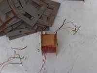
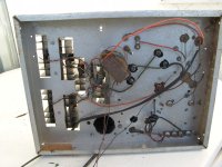
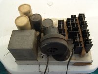
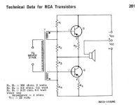
The primitive Totem Pole circuit was found in the RCA Transistor manual. I simply super-sized it using three silicon transistors in parallel for each half. This thing paired with a DIY germanium preamp went in between my guitar playing and 8 X 12 inch speakers to create the loudest "thing" in the neighborhood. The workmanship is rather crude, but I built this thing when I was 15 years old (1968) with only a hand drill, a nibbling tool, and a soldering gun. I found it in 2007 after a hurricane destroyed the shed that it had been sleeping in for 20+ years. I plugged it in (outdoors) and it blew the fuse, so I jumped the fuse and plugged it in again to see one of the power supply caps vent, so I took off the heat sinks and the DIY driver transformer and trashed the rest. I took the 40 year old transformer apart to see how well the masking tape insulation held up and was quite surprised to see it mostly intact despite a serious soaking from the storm and a week of baking in the sun to dry. The transformer was wound on a fried Radio Shack power transformer core and bobbin.
My professional electronics career went a bit out of order compared to most people. I started on the line at Motorola assembling and tuning walkie talkies and worked my way up to an engineer designing them. Then Motorola paid for me to go to college for an engineering degree. As with most engineering degrees I had to build a senior project. Mine involved a Universal Tiger amp board, four Plastic Tiger amp boards, and a DIY power supply to power all 5 amps in a car. Those were the last of the Tigers that I built, and most of the boards had been built several years earlier.
My home stereo consisted of mostly Carver and Phase Linear stuff until I traded my first car (still drivable in the 90's) for an old Scott tube amp. After some fixing, it kicked all of the Carver / Phase Linear stuff right out of the stereo rack.
Attachments

That would be a cascode.I suspect a dual-gate MOSFET simply consists of two MOSFETs with the drain of one connected to the source of the other. If so, you might as well connect two ordinary MOSFETs in series.
If you tried to apply feedback from the upper drain to the upper gate, the upper mosfet's source and the lower mosfet's drain will just follow the upper drain, no feedback.
The situation with a dual gate mosfet is different because both mosfets share the same substrate;
you can't do that with two separate devices.
After all it is the voltage potential between gate and channel (which resides in the bulk) which determines the gate characteristics.
That parameters in the datasheet are referenced to the source is due to the fact that the substate is connected to the source and usually not available on a pin.
I, too, have a box of BF961 dual gates and they are still on sale for a buck:
https://www.rf-microwave.com/en/vishay-telefunken/bf961/n-channel-mosfet-amplifier/bf961/
Like the 3N211 mentioned earlier they are tiny RF devices limited to some 20 or 30 V drain-source.
But what is more restrictive is that both gates have protection diodes which limit gate-source voltages to below 6V.
Unfortunately I don't have the data for the R values for that old C Tracer picture, except that it was a 21HB5 Sweep tube with Crazy Fdbk and cathode drive for input. The gain was clearly a little low judging by the reduced plate voltage excursion in the graph. If you increase the resistance between the plate and grid2 the gain should go up, but the "linear" quality may go down.re: Sorento: It may be extremely linear with more than 100% feedback but this wire seems to have no gain at all, at least no voltage gain.
Yes, but only a few Volts. The Crazy Drive function works by current draw of grid1 reducing the voltage swing on grid1 at higher plate currents. (or grid2 voltages) So operation starts with grid1 control at low currents and transitions optimally to grid2 control at higher currents. Some optimization of the resistors is required to get a smooth constant gm curve set. Grid1 current should typically be prop. to SQRT of cathode current, and apparently reduction of grid1 control by divider action (lower grid1 Z ) effectively reduces the combined grid2 and grid1 3/2 power law to 2/2 law over the usable range. At least that's the "theory".So G1 is always positive with respect to the cathode ... ?
Last edited:
It might be possible to just use grid2 alone for Crazy N Fdbk with a high enough "Schade" resistor to get grid2 gm to drop off (from grid current Z reduction) for a linear result. The gain might be too high then. don't know. Grid1 could be biased negatively then.
The situation with a dual gate mosfet is different because both mosfets share the same substrate;
you can't do that with two separate devices.
After all it is the voltage potential between gate and channel (which resides in the bulk) which determines the gate characteristics.
Not really. It's mostly the gate-source voltage although the bulk-source voltage also does something. In the CMOS IC processes of 30 years ago and for a MOSFET biased in weak inversion, the transconductance from the gate-source voltage to the drain current was usually about twice as high as that from the bulk-source voltage to the drain current. Bulk effect has since been reduced in each and every new IC process. I don't know about the processes used for the BF981 and such.
By the way, the way we make a cascode on a chip is usually with a shared bulk. Assuming a P-type substrate, isolating bulks is possible for PMOSFETs and for NMOSFETs in processes with deep N-well, but it costs extra area and results in extra parasitics.
I think you have a point about there not being much point in feedback from the drain to the gate of the upper MOSFET, but I think the same holds for a dual gate MOSFET.
Last edited:
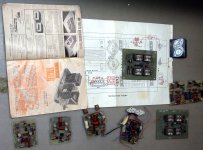
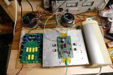
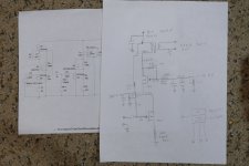
The UNSET amp board is here along with its schematic.
The FETSET breadboard is here along with the schematics and a version with the bigger heatsink needed to get 25 WPC.
Both amps make about 25 watts at the edge of thermal meltdown. The tube amp needs about 600 volts and the solid state version runs on 300 volts and eats 740 mA (over 200 watts to make 50 watts of audio). They sound very similar. Almost 20 years ago I stuck some silicon in a 300B amp to create the TSE amp. At first there were many haters, some even saying that I should call my company Transistorlab. That eventually died off as the word of how it sounded spread......but I don't think the world is ready for a Tubeless amp with OPT's yet.
Attachments

Well, is the output transformer really necessary here? Looks to me like it could be replaced with a choke or a CCS if the voltages and currents are adjusted?but I don't think the world is ready for a Tubeless amp with OPT's yet.
Fuling,
If you remember the 6 transistor AM radios with 9V batteries, from the 50s and 60s,
95% of them had an interstage phase splitter transformer, a thermistor bias stabilizer, and a push pull output transformer.
Practicality, and longer battery life, were the order of the day from marketing . . . to the engineers who designed the radios.
And, at least one McIntosh solid state Hi Fi Stereo amplifier had an output transformer to give multiple optimum output taps for different impedance loudspeakers.
Then there was at least one Allied Radio Stereo Hi Fi amplifier that used an interstage transformer with two floating phase splitter windings . . .
to drive the output transistors. That made biasing the output transformers simple.
Engineering Solutions Abound!
History goes around, and history comes around.
Last edited:
One just needs to look through all the amps and designs posted by Nelson Pass and his followers to know that it has been done that way several dozen times. I remember a Pass amp that uses incandescent light bulbs in place of the CCS. All of the voltages seen in my testing could be substantially reduced if an 8 ohm load was the target, but that has all been done already. The large board seen in my pictures was designed and laid out by forum member RA7 in a thread in the Pass Labs forum. Several users were using that board to feed a zero voltage gain follower of some sort to drive a speaker. Since I last looked at that thread a newer board has been designed and the thread has seen over 1200 posts.Well, is the output transformer really necessary here? Looks to me like it could be replaced with a choke or a CCS if the voltages and currents are adjusted?
https://www.diyaudio.com/community/threads/schade-common-gate-scg-preamp.380487/
Some time ago I found three surplus 5 Henry @ 5 Amp chokes that I bought for the metal scrap value. I experimented with several follower designs both tube and solid state that simply wired the speaker across the choke. The few mV dropped across the DCR of the choke didn't bother the speaker.
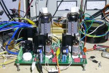
In this case I grabbed two pair of low impedance Toroidy OPT's at a good price as TME was discontinuing the Toroidy line. This amp will be a home for the 600 ohm pair. I have seen 25 watts flow through them at 20 Hz with 2.5% THD, and they sound good too. I have a larger heat sink than the big one in the picture, but the next experiment will test some CPU coolers to see if they can really handle 100 watts of heat as claimed. I have a good collection of them since I have been building PCs since the 1980's.
Attachments
- Home
- Amplifiers
- Tubes / Valves
- Designing a solid state tube?