Actually not for the same project but almost identical, indeed the layout of my PCB is different with 2 ground plane, one with Power GP on the top and one with Signal GP in the bottom with connection at the star Ground of the PSU. No ground plane under the transfo and the psu section. i just finish populated the PSU..will let you not the result of noise and ripple courant.
Attachments
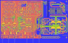
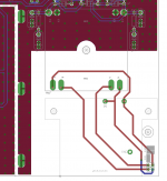
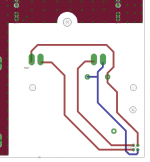
Here is an early look at the pcb design with the ground planes peeled back away from the HV area.
The Ground connection from the Power Inlet module is no longer connected now.
I would welcome suggestions about hot best to connect that ground. There is a spade connector at the butt end of the power inlet that has a wire linking the case to the ground, but the ground on the pcb is no longer linked to that ground now (the earth that is). Anyone can criticize please?!?
Attachments
For info, the main ground plane is the one on the bottom layer, and I kept the breaks to a bare minimum there, although it's impossible without some straps to avoid breaking a few spots in the ground plane, I didn't want any straps in there.
Any top layer ground plane is just extra. And all is tied with loads of vias.
What I'm wondering about is the grounding aspect of things now.
Any top layer ground plane is just extra. And all is tied with loads of vias.
What I'm wondering about is the grounding aspect of things now.
On grounding, I would expect that solid ground plane to be great for the signal parts.
Just try to keep the rectification area isolated from the larger small signal area. I've not reviewed the schematics from that viewpoint.
Just try to keep the rectification area isolated from the larger small signal area. I've not reviewed the schematics from that viewpoint.
I moved one trace from the HV primary side area to the other side and I'm tweaking the vias, position and size, making them smaller and tented for the next version.
I hope the prototype won't reveal too many issues, so not so many tweaks will be needed, or at least as minor as possible.
I'll re-post the schematics next, for those who have not started reading the thread from the beginning.
I hope the prototype won't reveal too many issues, so not so many tweaks will be needed, or at least as minor as possible.
I'll re-post the schematics next, for those who have not started reading the thread from the beginning.
Attachments
Just try to keep the rectification area isolated from the larger small signal area. I've not reviewed the schematics from that viewpoint.
Could you elaborate on this please?
Having a full ground plane pretty much blurs the star grounding, more or less, although I did some partial split where the shield is supposed to be, kind of making the star ground "area" that small area joining the 2 main ground plane. It's not positioning it near the rectifier bridge and big caps...
Any hints on how best to connect that power inlet ground? It's now no longer connected, having pushed the ground planes back from that area.
The case would still be grounded by that extra wire from the power inlet's butt plug 😀 (see 3D renderings for that part)
The case would still be grounded by that extra wire from the power inlet's butt plug 😀 (see 3D renderings for that part)
There is plenty of isolation (creepage) around traces in the primary area, except it gets cramped up at the voltage selector header, which has a 2.54mm pitch. Can't really be helped, but if someone differs, please criticize this..
And by the way, to clarify, the main ground plane is the one on the bottom layer. And whatever was left unused on the top layer is just extra ground plane. All stitched with vias.
The shield is probably not actually needed, but I put one there, optional, just in case. I'm only thinking about the transformer's radiation, which should be minimal anyway, being a toroid, and it's a small low powered one. Plus there is some buffer room around that transformer, as far as the small signal area is concerned. Probably out of reach of any magnetic stray field.
I'm still wondering about the possibility of the device being plugged into a wall plug with no ground. I think trying to go "double isolation" might be difficult, and costly.
May be you should use GLB.
One side to the Chassis and Intlet power and the other side to your GND PSU
One side to the Chassis and Intlet power and the other side to your GND PSU
Ok, I figured I'd insert a plain and simple ground isolator (dc blocker...) in that incoming earth connection from the power inlet module.
This does increase the part count, but definitely not by much, and those are very cheap ones.
I don't think it needs anything more than that. I don't think it needs to use 4 diodes either.
There is enough spare space around the power inlet module and the transformer, so that's easy to add it there.
See attached updated psu schematic. Any comments? Fire away...
Attachments
35A bridge for a power amp, perhaps.
But for this, it would be way way way overkill!!!
The fuse in that power inlet module is only 100mA and even that is well above what is actually necessary. The transformer is only 5VA.
A small dc blocker should suffice and will never be stressed. In case of a really bad fault, at the most we could blow diodes or whatever, maybe with a lightning strike...
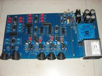
Finally received a few of the missing parts to bring the PSU part of this board to a testable level. Still missing a few things though, but nothing critical, like the heatsinks, hardware...
I can't put my hands on a scope right now and all I have is a digital meter (very old one) to test things. Nothing handy to do a gradual powering up..
Anyway, I did power it up and although at first it was odd with something like over 20V or each rail output, after messing around with the voltage adjustment trimmer, which isn't the right one because I haven't got the good one yet, I was finally able to do voltage adjustment for the positive rail, which came to a nice 15V, and so at least that much of it works.
Something is wrong though, with the negative side, with an output of some -8V and change, which doesn't want to adjust with the symmetry trimmer, which commands the opamp doing the tracking.
That trimmer is also not the right one, because it's part of those things I'm still missing.
With only an awkward meter with crappy leads to test this, it'll take some doing to figure out exactly what the deal is.
It's not hugely complex, so there can't be much there to go wrong.
The negative regulator gets its setting from the opamp that reads from the other side, which is nicely at 15V, so there may just be something fishy going on with that opamp, unless that brand new negative regulator is faulty somehow..
Getting there though..
Ok, although it took quite some time to arrive at this hypothesis, I think I may know what's wrong with the negative side not tracking properly from the positive.
I made a spice sim for that tracking PSU and tried a few variants, and it does work in sim, as long as the opamp's supply doesn't come from the PSU outputs, and I also breadboarded this and found pretty much the same thing.
So it seems that concept I took from somewhere on the net, which is actually quite spread out, that uses the regulators' outputs to supply the opamp, doesn't work!
I suspect this may be because the regulators need to "start-up", with their adj pin at a certain set voltage, and if the opamp that is to provide that voltage isn't powered up because the regulator hasn't properly started up, then it's a non starter, a loop from which nothing good can come out.
So I altered the PSU scheme a bit, by making up with zeners the supplies for the opamp, taken from "before" the regulators, on the non regulated side (new sch attached), and this works properly in sim and in reality on a breadboard.
I will have to tinker with the prototype pcb to make up that better supply for the opamp, and I suspect this might work properly then...
Attachments
Alright, after tinkering with that prototype pcb, "air-wiring" that extra zener supply stuff for the tracking opamp, I'm confirming success, with a properly working and tracking PSU.
It doesn't look pretty with all that stuff floating around the pcb, and I had to cut 2 traces to insert that separate supply, but it's working nicely now, with a nice 15.00V adjusted with exact tracking.
Updated the PSU schematic a little (attached).
The prototype doesn't have the ground isolator, but works fine.
Next step will be populating for the filters..
Attachments
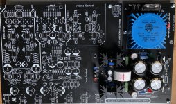
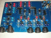
Making some progress building the prototype.
Posting a bit of porn to show this here 🙂😀
I figured out how to make the PSU track properly and work right, which necessitated a few ugly shenanigans with air wired parts, but it now works.
The way I had done that PSU was from a concept widely available on the net, but it has a flaw, it doesn't work for real, not even in simulations, at least not as-is. What's wrong with it is that the tracking opamp is supplied from the regulated output, which seems sensible as it doesn't require a separate supply for the opamp, but the LM3xx regulators don't "start up" if they're not "driven" properly, as is what happens for the negative side being driven by the opamp, which is in turn powered by that supply which hasn't properly brought up its negative side. Circular issue.
This is fixed simply by making up a separate supply for the opamp, made from the unregulated supply "ahead" of the regulators, so the opamp works right and drives the regulator properly and the tracking then works properly.
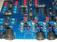
So it required a tiny bit of surgery on the pcb, with 2 traces cut and then I air-wired the extra supplies, with zeners/resistors and caps, and voila!!! Works perfectly now.
So I proceeded with populating the rest of the xover, although still missing a few odds and ends at the moment, it's very close to being done.
I don't know yet how I will do the testing, with my current very limited means, but I'll figure something out..
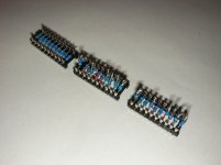
The swappable sockets setting the xover frequencies were a bit tough for me to assemble, with my diminished capabilities, but I managed. Better this than trying to screw around with SMT! 😱
Posting a bit of porn to show this here 🙂😀
I figured out how to make the PSU track properly and work right, which necessitated a few ugly shenanigans with air wired parts, but it now works.
The way I had done that PSU was from a concept widely available on the net, but it has a flaw, it doesn't work for real, not even in simulations, at least not as-is. What's wrong with it is that the tracking opamp is supplied from the regulated output, which seems sensible as it doesn't require a separate supply for the opamp, but the LM3xx regulators don't "start up" if they're not "driven" properly, as is what happens for the negative side being driven by the opamp, which is in turn powered by that supply which hasn't properly brought up its negative side. Circular issue.
This is fixed simply by making up a separate supply for the opamp, made from the unregulated supply "ahead" of the regulators, so the opamp works right and drives the regulator properly and the tracking then works properly.
So it required a tiny bit of surgery on the pcb, with 2 traces cut and then I air-wired the extra supplies, with zeners/resistors and caps, and voila!!! Works perfectly now.
So I proceeded with populating the rest of the xover, although still missing a few odds and ends at the moment, it's very close to being done.
I don't know yet how I will do the testing, with my current very limited means, but I'll figure something out..
The swappable sockets setting the xover frequencies were a bit tough for me to assemble, with my diminished capabilities, but I managed. Better this than trying to screw around with SMT! 😱
Attachments
- Home
- Source & Line
- Analog Line Level
- Designing a 4 way active crossover filter