It wouldn't look too bad in a sheet metal aluminum case, especially if anodized.
I would go for black anodization.
A sheet metal case is simple to make, for a properly equipped sheet metal shop.
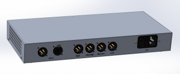
Case would be 2 parts, top and bottom, with just 4 screws to assemble it.
Removing the top allows easy access to everything, to tweak levels, PSU voltages, change/rotate component sockets as needed. Then close the box and no more accessible things to fiddle with that would alter how it works. No knobs or switches to touch, only the on/off switch on the power inlet module, with access to its built-in fuse in case of need.
The C14 plug allows using whatever power cord is used in the country where it's to be used, with the other end plug matching what is used locally.
And before plugging it in the first time, the voltage jumpers allow easy selection for the local line voltage.
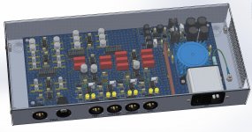
The PSU output jumpers are left out at first powerup, so the +15V can be adjusted, and then the -15V tracking tweaked to match it. Then power it off and wait for cap discharge before putting those PSU jumpers back on, before powering up again with everything online.
Easy to check the PSU voltages with a digital meter while the jumpers are off, with the jumper pins bare, but being careful not to short them with the meter's leads while measuring.
Before plugging any amps in the first time, the proper operation of the filters should be checked and levels might be good to be set low, so they can be raised afterwards when amps are plugged in and a signal passing through.
Assembly could hardly be made any simpler and easier, with only one wire inside the case, the ground wire, which needs 2 crimped connectors.
Then it's only quick and simple assembly, once all parts have been soldered on the pcb.
I would go for black anodization.
A sheet metal case is simple to make, for a properly equipped sheet metal shop.
Case would be 2 parts, top and bottom, with just 4 screws to assemble it.
Removing the top allows easy access to everything, to tweak levels, PSU voltages, change/rotate component sockets as needed. Then close the box and no more accessible things to fiddle with that would alter how it works. No knobs or switches to touch, only the on/off switch on the power inlet module, with access to its built-in fuse in case of need.
The C14 plug allows using whatever power cord is used in the country where it's to be used, with the other end plug matching what is used locally.
And before plugging it in the first time, the voltage jumpers allow easy selection for the local line voltage.
The PSU output jumpers are left out at first powerup, so the +15V can be adjusted, and then the -15V tracking tweaked to match it. Then power it off and wait for cap discharge before putting those PSU jumpers back on, before powering up again with everything online.
Easy to check the PSU voltages with a digital meter while the jumpers are off, with the jumper pins bare, but being careful not to short them with the meter's leads while measuring.
Before plugging any amps in the first time, the proper operation of the filters should be checked and levels might be good to be set low, so they can be raised afterwards when amps are plugged in and a signal passing through.
Assembly could hardly be made any simpler and easier, with only one wire inside the case, the ground wire, which needs 2 crimped connectors.
Then it's only quick and simple assembly, once all parts have been soldered on the pcb.
Attachments
Hi Sir,
Completed the build and tested?
Thanks and regards,
Sumesh
Hi,
I have 5 pcbs and started gathering the parts to build the first one.
I'm starting with the parts necessary for the power supply part of it, so I can test that first, because I don't have the means to get all of the stuff needed all at once, so I need to go stage by stage, and the best starting point is getting the power supply to work properly.
I have almost all of the parts to make the power supply to work now, and I should be getting the few last needed ones within the next few weeks.
I will be testing that power supply real soon.
At the moment I'm not bothering with a case, just the circuit, so I can get something working real soon.
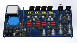
I will put all of the ICs on sockets, and the design was also made for all of the filter's parts to be on swappable sockets as well, so if need be, the values can be changed to alter the cut off frequencies.
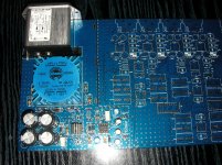
Here are a couple of photos of the pcb with most of the power supply related parts on it.
I'm missing a few things still, including the fuse drawer for the power inlet module, and hopefully I'll get this early next month, so I can finally test that part of it.
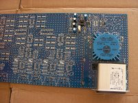
The pcb was made as a prototype and the vias aren't tented. But the next iteration of that pcb will have all vias tented and they will be smaller. The pcb will look different at that point.
I'm missing a few things still, including the fuse drawer for the power inlet module, and hopefully I'll get this early next month, so I can finally test that part of it.
The pcb was made as a prototype and the vias aren't tented. But the next iteration of that pcb will have all vias tented and they will be smaller. The pcb will look different at that point.
Attachments

Happy to see the boards taking shape..
Where can I find more details on the power-supply?
Thanks and regards,
Sumesh
Where can I find more details on the power-supply?
Thanks and regards,
Sumesh
I posted all the schematics and board designs a few posts earlier, about post #93ish...
One small change I do plan to make later in the pcb layout is to make all the vias smaller and tented. Other than that, I'm not planning any more changes so far. Testing might reveal something, maybe, we'll see about that. If tweaks are required, they'll be made then.
The PSU has an extra opamp to make it more symmetric in its behavior, so its voltages are staying as equal as possible all the time. The extra opamp is a tracking system to force the negative side to track the positive one.
This was done to minimize the chances for bad behaviors from some types of opamps that don't like it when their rails aren't equal. Some tend to stick to a rail when their supply rails aren't the same. The opamp I chose isn't known to exhibit that bad behavior, though others might want to build this with other opamps and having a better behaved PSU should help minimize odd behaviors.
Plus a PSU with rails tracking each other during power up and down should minimize pops and clocks...
One of the most important design goals was to avoid any loose wiring, and I think this was achieved, with only one short wire that can't be avoided, the ground wire to the case from the power inlet module. Should make it an enjoyable and clean build. I just hate wires all over the place..
My next step right now is to finish the power supply part of the build so I can test that. I need to gather more parts, which I should be getting shortly. Will post updates with photos when this is done. Soon.
I have 5 blank pcbs, made by JLCPCB. They turned out looking very nice. I'm only building one prototype for now.
Large untented vias in a prototype board can be very handy for probing signals - stick a piece of 0.6mm solid core wire through the via and clip 'scope probe to the other end.
Nice project, not many people do active analog XO.
I cheated and modified an existing active 3way and modifed subwoofer bandpass filter boards. So its lots more wiring in the box. Still its quiet.
As stated earlier, as long as your drivers can manage 1 octave past your XO points, the electronics will dominate. Especially with LR4.
You can measure your system in a relatively inexpensive way. You can get an inexpensive microphone and use freeware REW (not just for rooms) to measure. It might help you determine the XO points and setup your EQ. There's lots of help available (here) for REW if you need it.
Measurement Microphones - Parts Express
REW - Room EQ Wizard Room Acoustics Software
I don't want DSP. I prefer analog and try to avoid anything digital in the signal's path if I can manage.
I chose my xover points carefully according to the drivers used. They all have plenty of bandwidth and I chose those xover points not just for their frequencies but also for how much energy there is in each band. My tweeters are only 20W, so I wouldn't try to cut those overly low. My hi-mid drivers are compression and 80W, so more headroom there, but still, I wouldn't want to cut those too low as well, but since my lo-mid are very capable to reach near 6khz, there is lots of headroom there as well.
Some have suggested temporarily using a mini-dsp and a few other things to get a handle on testing things. I'll see what I can get when I get to that point, but all this stuff is expensive, even though DIY, so it'll be some time for me to get all I need.
This xover design is meant to be customizable, with everything xover point related on swappable sockets, so anyone can choose and change their xover points at any time as needed.
I had considered the state variable scheme, but settled on ordinary stuff because of how problematic it is to get those multi-gang pots..
I don't think I'll need to alter my chosen xover points, they should be fine as I chose them, so I think the adjustments will exclusively be done at the equalizer (not dsp).
Got a few more parts lately, to assemble more of the xover.
I'm focussing on the power supply part of it first, so I can test this and I can't get everything all at once.
I'm about to do more soldering shortly and then do the test. But it's a simple thing, the power supply should work out of the box (hopefully). I'm being careful and I test many of the parts individually before soldering them, especially the electrolytics, but also double check on the resistor values, diodes, etc...
About my speaker drivers, since it's 4 ways and the drivers all have far more bandwidth than they will be asked to reproduce, they should be quite comfortable in their assigned job. The xover frequencies chosen are also picked according to what part of the spectrum each driver is best at, even though the 15in low-mid driver has a capability to go lower than the 18in low driver, still, the 18in driver is more capable to produce very large volumes of the lowest frequencies.
Here is an update to the xover build. With just about all the parts related to the power supply populated, which should allow testing that section shortly.
I didn't install the heatsink because I'm missing some of the mounting stuff, but that won't prevent testing and adjusting the PSU.
I'm missing a key part though, the fuse, which I was expecting to receive a few days ago, but maybe the postal system got slow because of that pesky virus 😡
Hopefully I'll get the fuse in there in the next few days and I should be able to power this up...
Attachments
Lovely to find this subject.
im working with similar project.
My first try is with some chip amp (lm1875)
To see if i can manage to match all the drivers spl and frekuensi range.
im working with similar project.
My first try is with some chip amp (lm1875)
To see if i can manage to match all the drivers spl and frekuensi range.
SpookyDD,
I am a big fan of active crossovers - and am sure you will love the result.
I am much less sure about the PCB around that mains connector and on board transformer. You would seem to have ground fill around and under the transformer and power connector.
This need not be a big issue, but you must be very careful to have appropriate clearances between the mains traces and low voltage traces. This includes the ground.
Any fault between those mains traces and the ground fill will propagate to the rest of your system and in the case of such a fault create a hazard through the whole of your sound system being at mains voltage.
OK, that might come across as alarmist. Just looking at your layout, it would seem you have only a minimal clearance (a fraction of a mm) between the ground and mains connected traces.
If the diagrams I am looking at are correct, I implore you to reconsider connecting this to the mains!
I hope that the PCB's you had manufactured address this issue.
IEC-60950-1 and other standards give sound advice here. Most manufacturers use somewhat greater clearances to be sure.
As a general rule, I would be looking for a good 5mm clearance between the mains connected parts and any LV part. (Remember that the creepage distance for mains voltages must include transients that will be seen on the mains - for 220V mains the transients the standards consider are 800V pk and 1500Vpk for class I and II).
In your case I would have stopped that ground plane well on the "low voltage side" of the transformer.
I hope that I have not been unnecessarily alarmist - and that I have really misundersood the plots of your PCB traces.
Phil
I am a big fan of active crossovers - and am sure you will love the result.
Will surely beat the hell out of that crappy "temporary" set up that I had for so many years with 😱 passive 3 way

I wanted to go active since the early 80s, and never got around to finishing a design, so I'm getting real close now, finally!
I am much less sure about the PCB around that mains connector and on board transformer. You would seem to have ground fill around and under the transformer and power connector.
Now you got me wondering if I left out some detail. I assume you're thinking about stray magnetic field from the transformer getting into those ground planes in the pcb below. I didn't worry about that, but that may require a little more thought. That transformer is toroidal, so far less to worry about than those legacy E-I types. I'll have to give that some thought. But I surely will find something out soon, maybe, when I flip the switch. I should be getting the last few things needed for that shortly (I hope. With the quarantine and all...)
This need not be a big issue, but you must be very careful to have appropriate clearances between the mains traces and low voltage traces. This includes the ground.
Which low voltage traces are you referring to? The ones on the secondary side?
Any fault between those mains traces and the ground fill will propagate to the rest of your system and in the case of such a fault create a hazard through the whole of your sound system being at mains voltage.
I think I may have to tweak some details there, to get some galvanic isolation, but the ground I'm not sure about, although perhaps a ground lifter could be inserted, but on such a small powered thingy, not sure that will do much, and I didn't worry about possible DC on the mains...
OK, that might come across as alarmist. Just looking at your layout, it would seem you have only a minimal clearance (a fraction of a mm) between the ground and mains connected traces.
I guess that's something I need to review some more and possibly needs tweaking, with some larger isolation, for those traces. This is for 220V mains after all.
If the diagrams I am looking at are correct, I implore you to reconsider connecting this to the mains!
I hope that the PCB's you had manufactured address this issue.
IEC-60950-1 and other standards give sound advice here. Most manufacturers use somewhat greater clearances to be sure.
Could you point to specific areas of concern?
In your case I would have stopped that ground plane well on the "low voltage side" of the transformer.
And not have ground planes in the high voltage areas then?
I hope that I have not been unnecessarily alarmist - and that I have really misundersood the plots of your PCB traces.
If something was done wrong, then corrective action is required and something must be learned in the process.
PS: you do love vias, don't you!
Those are meant to tie up the ground planes as much as possible, nothing wrong with that, is it?
But for the high voltage mains related area, I would welcome any input..
Should I push back the ground plane away from the high voltage area? That is one question.
But there is one spot where I don't see much that can be done: the voltage selector jumpers, which have a regular pitch of 2.54mm (.1").
But there is one spot where I don't see much that can be done: the voltage selector jumpers, which have a regular pitch of 2.54mm (.1").
There is nothing wrong with the vias - it is a feature you chose and is a nice thing.
The clearance between mains connected traces and ANY low voltage part needs to be able to withstand not only the peak mains voltage but also transients on the mains supply as these occur.
As noted above the transient standard used for commercial equipment is 800 / 1500v
You should have close to 5mm clearance between LV and mains traces.
I would push the ground fill back to achieve this.
I am not seeking to be nasty - i think this is a good looking design.
I am sure you will end up with a great XO
The clearance between mains connected traces and ANY low voltage part needs to be able to withstand not only the peak mains voltage but also transients on the mains supply as these occur.
But there is nothing LV at all anywhere near the HV stuff, except perhaps that ground plane, so I guess that's what you're referring to.
But now I'm also thinking about something else too, with such a power inlet that pretty much insures there is a ground connection, logically the presence of the ground (earth) would be assured, but what if someone was to plug that nicely grounded power cord in a wall plug without the ground, then that earth link wouldn't be there and that would make the ground float on the device. I think I need to think some more about that aspect of it.
At least this prototype should serve to smoke out possible "bugs" or omitted safety details.
You should have close to 5mm clearance between LV and mains traces.
I would push the ground fill back to achieve this.
So that's something I'll have to tweak for a revised version. But for now the prototype should server its purpose to smoke issues out.
I am not seeking to be nasty
No offense taken at all, of course. This is constructive criticism and it's one good reason to post things like this on forums and share the work and whatever can be learned from it.
I'll try to re-think that HV area in the layout and tweak that ground stuff.
One other thing to think about is that extra shield I have placed between the small signal and the PSU area. It's also grounded, but now I'm wary of the grounding scheme. Will require more thoughts. And probably more tweaks there too.
I'll have to do all the tests on that prototype pcb. Hopefully not too many issues will come up.
One thing I did with the mounting scheme is to not have the ground on the mounting posts, but there is solder mask there anyway, and I had planed on using plastic mounting studs..
- Home
- Source & Line
- Analog Line Level
- Designing a 4 way active crossover filter