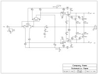
I've had this board laying around for a few years and decided to build a schematic for it. I've two questions about this thing???
1. Why would the designer use a TIP42c and a D880 for the drivers? Why not a TIP42c and its compliment, TIP41c? Or D880 and B834?
2. Is there a design name for this type of araingment, LTP. VAS, driver stage... I notice there is no bias adjustment and would not even know where to integrate one.
Any advice is welcome. I have not powered it up yet...
Scott
Attachments

Thanks Nico... Well I connected it to a 30-0-30 300w toroid and It started with no smoke! DC Offset is about 14mv Lt and Rt.
I measured for bias voltage across R39 and R41, with the fluke set to DC mv, I measured 0.000 Did the same across the others with same result.
HHMM... Now to temp heatsink it and see what it sounds like. Will post results
I measured for bias voltage across R39 and R41, with the fluke set to DC mv, I measured 0.000 Did the same across the others with same result.
HHMM... Now to temp heatsink it and see what it sounds like. Will post results
I think that you will have a lot of crossover THD, the output stages are not biased ON, No thermal coupling on the bias diodes, no local HF decoupling after the fuse, no anti latch diodes for speaker flyback, input stage not in the thermal loop (DC offset). It needs redo.
Audio1Man is right.
With four b-e to bias, two 1N4148 sets this amp in class B.
TIP42C and 2SD880 because these were available, leftovers?
Input diff's not in a DIL14 case anymore (THAT's?), but more of these common bjt's.
Small rectifier bridge, fits in the board edges.
Lazy incomplete design, left after some disappointment?
Take a good design and move the usable parts, trash the rest.
Odd way to draw Q5-Q7, mirrored, rotated, flipped. But readable.
No, that would give a conduction angle of less than 180°, so class C.With four b-e to bias, two 1N4148 sets this amp in class B.

It looks like a resonable design, all you would need to do is re-engineer the bias network. Pretty simple to pull out those two diodes and replace with a Vbe multiplier. A Vbe multiplier is a single transistor and two (or three) resistors.
Pull those two series diodes and replace with this:

Fire it up and adjust the pot for 10 - 15 millivolts across any of the four 0.5 ohm emitter resistors.
Fire it up and adjust the pot for 10 - 15 millivolts across any of the four 0.5 ohm emitter resistors.
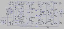
Here is what this type of topology should look like (below) - if the designer was not "lazy".
I've seen similar on Asian slave labor sub amps. Even those use zener regulated tail current sources.
Anywhere in between my example and the simple (lazy) version would work. "lazy" version would have crazy
DC offset , even with that blocking cap.
PS - this amp is "fully complimentary" ... Prof. Leach in Georgia,USA made it kind of famous. The "Leach amp" built by many a student.
It can .... with less lazy - be quite a "ripple eater" , giving cheap power supplies new life.
Attachments
Last edited:
Lying Asian power rating ,too. 120W/8R and maybe 200W/4R @ 50V rails. NOT 500 !!!
PS - wonder if the rubycon caps and output semi's are real ??
PS - wonder if the rubycon caps and output semi's are real ??
Thanks for all the info on this design. I've removed all the decent parts and tossed the board. I do think the 5200's and 1943's are fakes as the ones I have from old Soundstream amps are thicker and a bit heavier. I've had good luck LJM's stuff and Elliott Sound stuff.
At least there is now a schematic for this board that is sold on the net. People can make a choice before purchasing one.
At least there is now a schematic for this board that is sold on the net. People can make a choice before purchasing one.
- Home
- Amplifiers
- Solid State
- Design Question