Hi,
I'm trying to desing single ended GM-70 output transformer using nanocrystalline C-cores and I need some help because this is my first approach to OPTs.
Design assumptions:
Newbe ideas:
My first attempt:

Questions:

secondary:

Project files in attachement.
Thanks for any help.
Marek
I'm trying to desing single ended GM-70 output transformer using nanocrystalline C-cores and I need some help because this is my first approach to OPTs.
Design assumptions:
- core: double nanocrystaline C type cut core (same size as AMCC-400) per OPT
nanocrystalline material annealed in transverse magnetic field (the most narrow and linear B-H loop)
Bmax=1.25T - single center custom FR-4 bobbin
- 30W, anode current up to 100mA
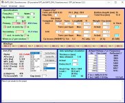
- using OPT_da desing tool
- winding with numeric winding machine
- OCC copper for windings (not for prototypes ofcourse)
- Nomex insulation (also in final version)
- for first try only 8Ohm output
Newbe ideas:
- number of turns in sections - an integer multiple of turns of single layer (to keep windings smooth)
- 17 sections (9 primaries in series and 8 secondaries in parallel)
My first attempt:
Questions:
- does it make any sense? 🤔
- Fo=30Khz seems to be low?
- bobbin is filled only in 50% (16,6 of 35mm) - is it a problem?
- should I be concerned about calculated resonant freq of primaries/secondaries?
secondary:
Project files in attachement.
Thanks for any help.
Marek
Attachments
Last edited:

1) You need to determine correct (real) permeability of your nano c-core (using variac, milli-ampermeter and test coil, designed for about 1.15T at 220V/50Hz), its not same as toroid one usually listed in data sheets. When nano-c cores are immersed in the glue and cut, real permeability drops to about 3000 - 7000. Stacking factor of nano c-cores usually is about 75%, so effective (useful) core cross-section is only 75% of geometric one.
2) 17 section not necessary in any case, 15 max. There is a long theory behind this, you can take it from transformer design books if necessary. In short - anything above 15 sections yields no meaningful results.
3) "B Total" must be down to 1.15T to make some headroom.
Start with p#1, without correct permeability with no air gap further calculations make little sense.
With the turns ratio it seems to be a 7k @8R transformer.
Taking the GM70 Ri into consideration I would not go more than 9 sections.
I had GM OPT's made with comparable Afe.
9 sections, 2P-2S-4P-2S-4P-2S-4P-2S-2P.
So 16 layers of primary windings in 5 sections, and 8 layers of secondary windings in 4 sections in between.
Thin isolation beween layers, fill the remaining height with isolation between primary and secondary sections using all height.
Primary wire 0.355 mm; secondary wire 0.67 mm when I am right.
Number of primary turns 16 x 188 = 3008; number of secondary turns 101.
With the number of sections you have in mind you will have too much primary to secondary capacitance at the cost of HF bandwidth.
9 sections is a good balance of capacitance and leakage inductance.
@LinuksGuru
1) Yes, I'll do such measurments. The desired permability will be adjusted by air gap.
Stacking factor already taken into account (0.8 in my case) - it is defined by manufacturer.
2) Ok I'll try with 15 sections.
EDIT:
with 15 sections:

1) Yes, I'll do such measurments. The desired permability will be adjusted by air gap.
Stacking factor already taken into account (0.8 in my case) - it is defined by manufacturer.
2) Ok I'll try with 15 sections.
EDIT:
with 15 sections:
Attachments
Last edited:
You propable want to use this pentode with feedback. If so, you can reduce Rp by the same amount.
As to your simulation, most important, strive for a better ratio of Bdct to Bac. Something like Bdc close to half of your choosen Bmax, Bac must be less offcourse. Jiggle the turns and the airgap till you get satisfying results. To find the rigth amount of interleaving start out with 1 primary and 1 secondary section. Use a equal amount of primary and secundar sections and SPLIT the primary, this will reduce leakage inductance. (if it looks impossiple to get satisfying results with the split winding approach you may still be forced to use unsplit windings to get Q down)
First try 2 prim, 2 secundary a.s.o and try to get sensible Q values. Since you have a lot of space and your windingwidth is comparable wide, you can increase the interwinding isolation to decrease capacitance and Q, and increases fo (reliefs also voltagedtress). If to many uninterleaved sections it may be necessary to look at the Rac/Rdc ratio, but thats to early yet...
Last edited:
@Marek, you can lower Rp (and thus, transformer primary winding requirements) by going with cathode feedback, e.g. 12 - 25%, but I don't know exact ratio. For example, Sansui AU111, with PP pentode mode 6L6GC at max spec, uses 5K output transformer with 12% CFB instead of conventional 6.6K.
May be someone more experienced can advise Marek?
May be someone more experienced can advise Marek?
Daanve, he asked about the transformer and the type of tube is unimportant, only Rp counts
so....GM70 is a triode.
Ri is around 1700 ohm.
More or less treat it as an 845.
Ri is around 1700 ohm.
More or less treat it as an 845.
Split load would have really a big advantage lowering Rp and even more so by lowering Ceff but is usually limited by driver voltage capability
Daanve, yeah, wrong Rp started that confusion.
I looked at russian tubespecs decades ago ... GK, GM, GU, but did not remember wich is wich and assumed must be the pentode with this Rp. My bad.
I bougth some Gu because they can run triodeconnected at much lower voltage, in many ways comparable to 2 KT88 in paralell, but i never got around to build anything with them, but they look great on my shelf 😉
Btw, what is the voltage swing on your GM ?
Thats what i gave, transformer advice, no?
Thats what i said: ...is usually limited by driver voltage capability, no?
Thats what i said: ...is usually limited by driver voltage capability, no?
Last edited:
- Home
- Amplifiers
- Tubes / Valves
- Design of C-core nanocrystalline GM-70 output transformer