did some measurements
hi Mooly,
The problem happens more often now, so at least I was able to get some measurements in the "fault" state.
I'm getting strange results for this one.
When playing ok:
B: 1 V
E: ~ 300 mV
C: ~ 400 mV
When in fault state (so relay tripped, no output to speakers):
B: 1.9 V
E: 1.3 V
C: 50 V (!)
Not sure how to interpret these yet :-|
I measured R631 at one end, it was about 8.75V.
But looking at the diagram, the voltage should be 8.5V, so that seems right?
Thanks again 🙂
hi Mooly,
The problem happens more often now, so at least I was able to get some measurements in the "fault" state.
1/ Connect the speakers to 'A' and when the fault occurs measure the voltage on TR611.
Measure all three terminals and record the result.
The expected voltages would be about 650 millivolts on the base, close to zero on the collector and the emitter should be at zero volts.
I'm getting strange results for this one.
When playing ok:
B: 1 V
E: ~ 300 mV
C: ~ 400 mV
When in fault state (so relay tripped, no output to speakers):
B: 1.9 V
E: 1.3 V
C: 50 V (!)
Not sure how to interpret these yet :-|
If the emitter is higher than zero then there is a problem with the switch or the wiring.
If the collector is high in voltage then either the transistor is open or the base drive voltage is missing.
In that case measure the voltage on R631 (either end) and see if that is present. If it is 7 volts or more then there is a problem around the driver transistor which we can look at.
If there is no voltage present on R631 then we are looking further toward the circuitry at the left.
I measured R631 at one end, it was about 8.75V.
But looking at the diagram, the voltage should be 8.5V, so that seems right?
Thanks again 🙂
Just trying to pick up from where it was all at 🙂
OK, this might be easier than you think. Look at the circuit you posted at the beginning of the thread and follow the emitter of TR611. The emitter should be grounded via the switch (this is why I say there should be close to zero on it and why the base should be at around +650 millivolts)
So at face value there is a high resistance somewhere. The switch is favourite tbh.
Does that make sense?
The emitter has to be at zero volts, anything else means a high resistance is present.
Attachments
If I understand all this correctly, the A/B/A+B switch is the main suspect?
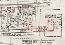
As a side note: there seems to be an error in the diagram: the rightmost RL602 (the one parallel to D607) should be RL603 (confirmed this on the circuit board itself and the printed wiring board in the service manual).
(RL603 is the relay for the headphones output)
(putting this note here in case someone runs into this and googles it 🙂)
Yes... look at that diagram and think it through 🙂
You can do further tests. Connect your meter black lead to where it says 38-3 which is ground.
Now measure the voltage on the 38-3 line at the switch. It should be zero of course as it should be a direct ground connection.
Now measure to 38-1 on the switch board. That should be zero volts as well because the switch should be connecting 38-1 to 38-3 through its contacts. If you have voltage on 38-1 then the switch is bad.
If by chance you don;t see voltage on 38-1 then you must then have an open circuit between there and TR611 but that would be highly unlikely.
I'm bypassing the switch now, by connecting 3B-1 to 3B-3, waiting to see what will happen 
(3B not 38 🙂)
(3B not 38 🙂)
So it is 🙂
Whatever happens, don't loose sight of the fact that you have been reading some voltage at the emitter of TR611. With those points shorted the emitter should (must) now be at zero volts.
Whatever happens, don't loose sight of the fact that you have been reading some voltage at the emitter of TR611. With those points shorted the emitter should (must) now be at zero volts.
Running a longer test now.Whatever happens, don't loose sight of the fact that you have been reading some voltage at the emitter of TR611. With those points shorted the emitter should (must) now be at zero volts.
The voltage at the emitter of TR661 is now at about 6 mV, which seems close enough.
(measured wrt. the chassis)
That sounds good. 6mv is caused by the relay current developing a small voltage across the wiring and PCB print and the route the chassis ground takes. All good.
That sounds good. 6mv is caused by the relay current developing a small voltage across the wiring and PCB print and the route the chassis ground takes. All good.
😀
It's been running for hours without a hitch now, thanks a lot for all your help.
Let me know if/when/how I can return the favour (my specialty is programming 🙂).
I'm impressed how well this amp still runs after 30+ years, but a bit puzzled how a switch that's used very little just fails (dirt buildup?).
Now to decide what to do:
- leave "A" connected (bypassing the switch)
- add a new single switch (so I can at least turn off speaker output when using headphones)
- open up the front and examine the switch
- buy replacement switch
😱
Thanks for the kind words (and offer) 🙂
As to the switch, well a lot depends on its construction and how easy it is to remove and so on. The failure mode could well be dirt/oxidation of the contacts or perhaps contacts that have lost mechanical tension.
I would say at this stage I would be hopeful of resurrecting it rather than replacing it. If it is an open type construction (any holes in it) then you could try some switch cleaner squirted into it.
If it will remove and open up then pretty much anything is possible.
There are other tricks as well such as temporarily getting it to switch a higher current in the hope that will help clear the contacts.
As to the switch, well a lot depends on its construction and how easy it is to remove and so on.
Now the amp is open, I might as well continue 🙂
The switch is very easy to remove (remove knob from the front, remove nut from front):


The blue wire is ground, red is for the "A" relay, white for "B".
Measuring resistance, the switch at B is fine: 0.8 Ohm, but at A it varies between 6 and 32 Ohm (!)(when wiggling the switch).
Tension in the switch seems good. I'll try to check for dirt now.
That looks highly promising. I would go as far as to say that those tabs on the frame could be gently closed and the switch dismantled and cleaned properly.
It also looks like a replacement by a generic 2 pole 4 way switch would be easy to do if needed. You would perhaps have to hard wire it rather than use a PCB but it should be straightforward.
You would use a 3 pole 4 way and just use two of the contacts.
https://cpc.farnell.com/lorlin/ck1031/switch-3pole-4-pos-metric/dp/SW04141?st=lorlin
Attachments

That looks highly promising. I would go as far as to say that those tabs on the frame could be gently closed and the switch dismantled and cleaned properly.
yes, it wasn't that hard to open it.
Those surfaces look pretty dirty:

Needless to say (maybe) but don't expect most modern affordable switches to last as long as that one. The Lorlin types are the rare exception, they are both good and affordable. New old stock Elma, Knitter, Grayhill are among the best.
Last edited:
I love how relatively easy it is to work on these amps.Needless to say (maybe) but don't expect most modern affordable switches to last as long as that one.
Here's the switch again, cleaned with some sandpaper and alcohol:

Reassembled, both A and B (and A+B) now measure 0.4 Ohm 😀
It was harder to bend those pins out again, on one side I put a small blob of glue instead.
If I remember correctly that Denon type has the infamous gold contacts speaker relays as well. You better replace those for silver based bifurcated contact relay types, preferably a bit higher rated with regards to current. Don't get me started on recapping (at least) the main filter caps 🙂 I guess fresh low ESR 15,000 µF 63V will fit. Even if the old ones still work new ones will improve performance as their ESR is way lower.
I reread the thread and see you mentioned PCB discolorations because of heat. A simple method is to drill (quite precise!) 2 or 3 mm holes between tracks where such heat buildup occurs to improve air flow. Electrolytic caps at such spots are best replaced as they were heated for years. I replace all electrolytic caps when I open such an old device anyway.
I reread the thread and see you mentioned PCB discolorations because of heat. A simple method is to drill (quite precise!) 2 or 3 mm holes between tracks where such heat buildup occurs to improve air flow. Electrolytic caps at such spots are best replaced as they were heated for years. I replace all electrolytic caps when I open such an old device anyway.
Last edited:
Excellent  hopefully they will last a while longer now. I see that one is actually a 4 pole as well but with only 2 contact sets fitted.
hopefully they will last a while longer now. I see that one is actually a 4 pole as well but with only 2 contact sets fitted.Thanks for all the recommendations.
Can you tell from the picture earlier in the thread if they are?

(adding the text info for google: DEC DH2TU 24 VDC 3A relay)
Is replacing those caps difficult? (doesn't seem like it)
The whole thing is very "mid range" anyway, e.g. look at the speaker connectors:

(though I've been very happy with this amp)
(eyeing an upgrade though 🙂)
And finally, what's the "non modular PCB design committee" 😕
If I remember correctly that Denon type has the infamous gold contacts speaker relays as well. You better replace those for silver based bifurcated contact relay types, preferably a bit higher rated with regards to current.
Can you tell from the picture earlier in the thread if they are?
(adding the text info for google: DEC DH2TU 24 VDC 3A relay)
Don't get me started on recapping (at least) the main filter caps 🙂 I guess fresh low ESR 15,000 µF 63V will fit. Even if the old ones still work new ones will improve performance as their ESR is way lower.
Is replacing those caps difficult? (doesn't seem like it)
The whole thing is very "mid range" anyway, e.g. look at the speaker connectors:
(though I've been very happy with this amp)
(eyeing an upgrade though 🙂)
And finally, what's the "non modular PCB design committee" 😕
Last edited:
measure esr?
I'm now inclined to go by "if it ain't broke, don't try to fix it".
Or maybe first measure ESR of the current capacitors.
would a cheapo meter like this one suffice:
LCR TC1 1.8" TFT LCD Display Multi meter Transistor Tester Diode Triode Capacitor Resistor Test Meter ESR LCR NPN PNP MOSFET COD|Multimeters| - AliExpress
?
Don't get me started on recapping (at least) the main filter caps 🙂 I guess fresh low ESR 15,000 µF 63V will fit. Even if the old ones still work new ones will improve performance as their ESR is way lower.
I'm now inclined to go by "if it ain't broke, don't try to fix it".
Or maybe first measure ESR of the current capacitors.
would a cheapo meter like this one suffice:
LCR TC1 1.8" TFT LCD Display Multi meter Transistor Tester Diode Triode Capacitor Resistor Test Meter ESR LCR NPN PNP MOSFET COD|Multimeters| - AliExpress
?
- Home
- Amplifiers
- Solid State
- Denon PMA-560 output relay tripping