I have a question regarding my preamplifier external psu
We have 4 transformers 2 in each channel all power up with the same mains switch on the front unit. I have read the its not good for the tubes the b+ and the heaters power up at the same time. So because i dont want to mess up with delay boards and too complex soldering, can i put a second mains switch seperate from the heaters because i have the advantage of separate transformers for hv and lv and power on heaters first and after a couple of seconds the hv or leave it as it is now in the risk of starting a fire again?
I forgot to tell you that the second transformer at each channel is output 15v ac for the preamplifier heaters and then goes to diodes, caps and 7812 SPARKOS regulator for a steady 12v dc and 6.3 v ac connected directly unregulated to the ECL82 tube HEATERS.
Is it safe then if i go with the 2 mains switches to power up the heaters transformer first but the ecl82 will have the heaters on but no hv to regulate which is coming next after i power on the hv transformer?
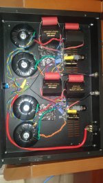
Attachments
Take a look at a switching scheme I've used many times for power amps. It uses two DPDT toggled wired so that whichever switch is closed first powers the heaters and the second powers the mains. No matter which switch you turn off first it powers off the mains first. Not original, I found it long ago.
https://www.timebanditaudio.com/300b/schematic.html
https://www.timebanditaudio.com/300b/schematic.html

Hearinspace i had a previous problem with short circuit and i blowup 34 diodes in the process until i found it. I believe.
This my previous post of real 2 days nightmare
https://www.diyaudio.com/community/threads/i-am-loosing-my-mind-here-please-help.426014/latest
When you are back again. in dyi after too many years you forget things about electronics that are critical.
This my previous post of real 2 days nightmare
https://www.diyaudio.com/community/threads/i-am-loosing-my-mind-here-please-help.426014/latest
When you are back again. in dyi after too many years you forget things about electronics that are critical.
I can't follow the description of your circuit in the linked thread. What are the Sparkos regulators powering if you have " 6.3 v ac connected directly unregulated to the ECL82 tube HEATERS. ")? Are there other tubes not mentioned? Schematics are very helpful .
Anyway, I don't see anything in any of the ECL82 data sheets that indicates a warm-up time is needed. If you're listening to it now with no problems and it's rated for job, the single illuminated switch you have in there now could be just fine.
The one comment I have is that If you ever do decide to try that "very clever" dual switching design then never forget that the filament transformer is always connected to the mains input.
You can't assume that just because you connected the transformer to Neutral from the chassis' power entry that there's no voltage on "Neutral" at the wall socket. If you work on the amp in any way, make sure it is unplugged. (I'd stick a reminder inside.)
This is not true, leave it alone.I have read the its not good for the tubes the b+ and the heaters power up at the same time.
Hearinspace the sparkos regulators are for the filaments of the preamplifier tubes 12AU7 x1 12AT7 x1 per channel in series 12v dc. The 6.3v ac direct from transformer is for the heaters of ECL82 x1 per channel which is the regulator for the b+. The hole PSU is in separate chassis as you can see from the pic.
Hearinspace the psu is working as swiss clock and the voltages b+ and filaments are extremely identical on both channels and the SQ of the preamplifier is at hole another level after the upgrades to the PSU
Merlinb you are in my head mate. I am afraid to put my hands again in there.
Hearinspace the psu is working as swiss clock and the voltages b+ and filaments are extremely identical on both channels and the SQ of the preamplifier is at hole another level after the upgrades to the PSU
Merlinb you are in my head mate. I am afraid to put my hands again in there.
This is really great in its simplicity and effectivity!Take a look at a switching scheme I've used many times for power amps. It uses two DPDT toggled wired so that whichever switch is closed first powers the heaters and the second powers the mains. No matter which switch you turn off first it powers off the mains first. Not original, I found it long ago.
https://www.timebanditaudio.com/300b/schematic.html
Is it safe then if i go with the 2 mains switches to power up the heaters transformer first but the ecl82 will have the heaters on but no hv to regulate which is coming next after i power on the hv transformer?
Running a tube heater alone without B+ (plate voltage) will not cause damage to the tube.
My suggestion would be to use a DP3T rotary switch or a DPDT On-On-On toggle switch instead of separate switches for the heater and HV so that you don't need to drill another hole in the front panel.
DP3T Rotary Switch
DPDT On-On-On Toggle Switch
No need to leave alone, there is a simple explanation:This is not true, leave it alone.
Except in tubes like magnetrons with huge cathode current density when hottest parts of cathode produce higher emission that heats them up more locally.
In amps the problem is opposite, discharged yet coupling caps that charge through control grids when anode voltage applied abruptly when cathodes are already hot.
- Home
- Amplifiers
- Tubes / Valves
- delay on the B+ or not