What about efficiency to define classes?
Didn't you like efficiency?
This is the only way to actually see if the amp is 'leaving class a', just to mention any one.
Didn't you like efficiency?
This is the only way to actually see if the amp is 'leaving class a', just to mention any one.
Alright then marco, if you'd be so kind as to offer a definition that describes the operation of the classic 2A3 SE use...and do please make mention of how it differs from the incomplete definition you propose for Class A.
cheers,
Douglas
I think I made my point earlier in the thread.
IMO, the phrase "class A" is better used to describe a mode of operation, not as a definition of what an amplifier is or isn't per se.
I rest my case.
Your AB amp spends 100% of its time in AB. It is not a bit of A and a bit of B; that condition is AB. Nothing more, nothing less.
The point being is that, to which you are referring is *NOT* Class A. There is more to the definition that both conducting 360 degrees. It is bias a little bit past the middle of the curves through which the load line passes.
If there is 50 mA available to a maximum positive grid swing of X volts, a swing of -X volts from idle must not cut off that phase. It is effectively two bridged SE amps working off their respective halves of a CT primary.
cheers,
Douglas
Some class AB are different from other class AB
(and, you know? You can see it by take a look at the efficiency ;-)).
It can be that one amp is polarized to be in class A until xW (and you could verify that with the use of a wattmeter to mesure, again, efficiency) and than class B (for a global efficiency that belongs class AB.
And another one can be class AB with only few milliW of output power in class A, and than class B, with efficiency that belongs class AB.
It is simple as it seems, and there is no other way to describe it.
Last edited:
Efficiency is an extremely poor way of determining an amplifier class. Class A efficiency varies from 0% to 50% (but less in practice). Class B efficiency varies from 0% to 78.5% (but less than this in practice). So you measure efficiency at 40%: which class is that? Fairly efficient Class A or less efficient Class B? Push a Class A amp well into clipping and you might appear to get increased efficiency, but it has not become Class B.iperv said:What about efficiency to define classes?
Didn't you like efficiency?
This is the only way to actually see if the amp is 'leaving class a', just to mention any one.
So what do we call the amplifier if the existing classification names are stolen and used just for mode instead? Using your definition of Class A it applies to almost all analogue circuits except at a switching point, because you can always draw a tangent to any smooth curve. Hence it loses useful meaning as a way of distinguishing different circuits.marco_gea said:IMO, the phrase "class A" is better used to describe a mode of operation, not as a definition of what an amplifier is or isn't per se.
When someone says that Class AB operates in Class A for small signals we know what they mean, even though they are misusing a term. Why can't we leave it at that: an understandable benign misuse? In a similar way, I know what someone means when he uses the incorrect term 'amperage'.
IMO, the phrase "class A" is better used to describe a mode of operation, not as a definition of what an amplifier is or isn't per se.
Classes of operation only refer to power amplifier. (ref. Millman).
Efficiency is an extremely poor way of determining an amplifier class. Class A efficiency varies from 0% to 50% (but less in practice). Class B efficiency varies from 0% to 78.5% (but less than this in practice). So you measure efficiency at 40%: which class is that? Fairly efficient Class A or less efficient Class B? Push a Class A amp well into clipping and you might appear to get increased efficiency, but it has not become Class B.
Yes, I agree in a general sense.
But you have to do it cum grano salis.
Anyway, class AB is not a rigid class of operation like class A and class B are.
Its theoretical efficiency is not so rigid as the one that refers to class A and class B.
And yes, it is a way to say that under certain circumstances it operates in class A, and than in class B.
There were some Single Ended RF amplifier Tube output stages that operated in class AB.....Class AB is used for RF 'linear' amplification of an already modulated signal.......Analog cell phones used FM modulation, and class C RF.......Digital cell phones were all GSM, and could also use class C....Qual Com digital cell phones..... EDGE, a special trick with more symbols, but no zero crossings
All cell phones made in the last 10 years or so use some variant of CDMA or LTE for their main mode of communication. Some do support older standards like GSM for compatibility. All modern modes do have an "emission mask" that is specified by the 3GPP (3rd Generation Partnership Proposal) and the communications authorities in the country of use (FCC and others). This is a strict set of standards governing how much RF energy in the transmitted channel can spill over into the adjacent and alternate channels. Meeting the emission mask is a careful dance between RF power amplifier linearity and efficiency. The amplifier operates in class AB. The typical efficiency on an LTE Power Amplifier (PA or RFPA) without special techniques applied to it is in the range of 20 to 25%.
The popular techniques for improving efficiency are:
Power Supply Modulation, varying the B+ in real time to give the PA just enough voltage to work at any given time. This is called class H in the audio world.
Pre-Distortion is where you carefully characterize the RFPA's distortion characteristics and create an inverse function to be applied to the baseband data in the DSP before modulation).
Peak limiting, and peak squashing are techniques where you limit the few points in the modulation (symbols) that would push the RFPA into high distortion. Here you purposefully transmit a bad symbol, counting on the error correction in the receiver to fix it. This is done to improve the emission mask performance while causing a mild degradation in EVM (Error Vector Magnitude). This is similar to cranking the volume up to where there is visible distortion on the scope, but the user does not hear it. If you have a scope and a tube amp (particularly an SE tube amp), crank it until you hear clipping on dynamic peaks (kick drum or bass guitar) then back up until the distortion goes away. THEN connect the scope to the output and look as the bass notes......there is still distortion that you are not hearing.
What does all this cell phone RF stuff have to do with audio and amplifier classes? Well, all of these techniques can, and have been used in audio amps, and all serve to blur the lines between classes. Using these techniques it IS possible to build a class A audio amp (by the 360 degree at full power definition standard) that achieves more than 50% efficiency.
So, as seen here there is no agreement on what constitutes a class A audio amp, and probably never will be, so let me toss another thought out there.
All popular SE tube amps are class A, right? The popular Fender Champ guitar amp (single ended amp with a 6V6GT tube) is known as a class A guitar amp. Do you think that it is still in class A when you plug a stomp box into it's input and drive it 20 db past clipping? NO WAY, but that is still a common misconception.
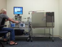
The first picture shows the big dummy (me) testing and tuning an LTE power amplifier to meet all the regulatory requirements while being subjected to temperature and load impedance variations. The RFPA is inside the big silver environmental torture chamber. The transmitted carrier is seen on the spectrum analyzer in the lower right, while the performance to the emission mask is watched on a specialized instrument in the lower left. A variable length line (trombone line) with a calibrated mismatched load attached is seen on top of the test chamber.
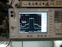
The second picture shows the PA operating cleanly (blue) with minimal spillover (meets requirements with margin) into the adjacent channels (techniques applied), and the same PA blasting the adjacent and alternate channels with spill over (2nd and 3rd order IM products) with the "magic" turned off (yellow).
Attachments
Greater than 50% in class A is possible when you use digital techniques to keep the voltage drop across the output device(s) just above saturation while still allowing the device to conduct for all 360 degrees of a cycle.
For this to work in an audio amp the output stage must operate as a follower. Either solid state emitter or source followers, or a vacuum tube cathode follower. This is needed to achieve high PSRR.
So assume a vacuum tube cathode follower operating as a class A output stage. Now attach it's plate to a high efficiency SMPS which is modulated with the audio signal such that the plate top cathode voltage across the output tube remains nearly constant and a low voltage, say 50 to 100 volts. Even if the SMPS is not 100% accurate the high PSRR of a follower will remove any "digital artifacts" in the audio output. My experiments showed that 10 bits of accuracy were enough.
An audio amplifier constructed in this manner will dissipate little power in the output tube, and little in the SPMS, so the total rolled output stage efficiency can exceed 50%. This can be used to extract more that the typical power output from a given tube. I was getting over 35 watts from a single 6AS7GA in SE with both sections wired in parallel. This entire design was prototyped and built for submission in a Circuit Cellar Magazine / Microchip design contest back in 2008. The magazine article was removed from their web site years ago, but I am the author so I have included it here.
Attachments
Thank you,
your work is awesome as usual!
I'm designing a prototipe for a class A push pull mosfet amp with 10bit potentiometers and Arduino allowing dynamic voltage control, for bias and power supply.
My purpose is to increase efficiency.
I don't think I can increase the efficiency over the theoretical 50%, but I can increase for sure efficiency from the point of view of a low /mid signal dissipating only the required power at the output stage.
But it's a long way.
The mode of operation. It was originally (and still is, IMO) an operational descriptor, not an architectural one. Unfortunately the issue was clouded when people also started naming architectures as 'classes' too (class D, class G etc). Those higher 'classes' are really a collection of devices working in a combination of the 'true' operational classes, A, AB, B and C. It would have been better to call such architectures 'Smith amplifier' or whatever.What becomes Class AB? The amplifier, or the mode of operation?
Last edited:
Class AB should not have gm-doubling.
Sure, marketing literature says nothing about gm.
How is >50% class A possible?
No. It is either A, or B. You can bias it at any idle current that tubes can afford. All in the middle between A and B is called AB, assuming some artificial tube curves.
Last edited:
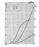
The sum of the two P-P tube's gm should be mentioned. For classical full over-lapped class A, the gm sum of the tubes becomes close to constant over the full signal swing range. Typical Gm versus grid voltage for an E55L tube is shown below (S curve). (the P-P over-lap has one S curve flipped around, and biasing determines the amount of over-lap.)
Without full overlap of the tubes conduction, the two gm curves sum to a flat bottomed V curve with rounded corners with the top of the "V" winging out besides. So clearly there is some distinction between full class A and just the class A portion of class AB.
The SS literature makes extensive reference to gm "wing" plots for P-P devices. Something similar needs to be done for P-P tubes. Both in the tube literature and on the bench with a simple analyzer/O'scope. This would make design so much simpler.
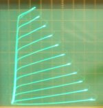
Then there is the "new kid" on the block, Twin/Crazy Drive (2nd pic below) which has near constant gm for each tube. Constant P-P gm sum should work out to a rather limited conduction overlap in this case. Making for an efficient "class A" equivalent.
Without full overlap of the tubes conduction, the two gm curves sum to a flat bottomed V curve with rounded corners with the top of the "V" winging out besides. So clearly there is some distinction between full class A and just the class A portion of class AB.
The SS literature makes extensive reference to gm "wing" plots for P-P devices. Something similar needs to be done for P-P tubes. Both in the tube literature and on the bench with a simple analyzer/O'scope. This would make design so much simpler.
Then there is the "new kid" on the block, Twin/Crazy Drive (2nd pic below) which has near constant gm for each tube. Constant P-P gm sum should work out to a rather limited conduction overlap in this case. Making for an efficient "class A" equivalent.
Attachments
Last edited:
The problem of gm doubling in ss amps is much worse, since they have much higher gm, and are very temperature-dependent. That affects the most critical listening region, adding dynamic distortions, i.e. distortions modulated by signal envelope that changes temperature of crystals instantly.
In tube amp it is a big problem when people fall for "No feedback" fashion building class AB amps without feedback.
In tube amp it is a big problem when people fall for "No feedback" fashion building class AB amps without feedback.
What becomes Class AB? The amplifier, or the mode of operation? ... If we say that an amplifier is Class AB then surely by definition that is a statement about the amplifier, not a statement about the amplifier plus a particular input signal? ....
"AB" should mean that the amplifier will work well (meet specs) in AB, even if it does small signals in A.
There are "A" amplifiers which can be pushed to AB, but don't do well. Grid blocking. Grid melting. Plate/screen melting.
How is >50% class A possible?
The "50%" comes from the way we customarily rate audio amplifiers, with SINE signal.
A "class A" amp tested with Square Wave approaches 100% efficiency. George's cell-phone work may have been pushing into this territory (I do not know). I have observed a 6550 SE audio amp idled at 34W Pdiss and putting over 24 Watts of Square Wave Heat into a (20W!) power resistor. However I do not like this bending of the classes, because the 6550 was clearly cut-off nearly half the time. Working on Sine and not-quite cut-off on the bottom, it was 13W Sine which is 38% eff which is typical for tubes.
I do not think it is right to attribute a class of an amp to a mode of operation. However, if to feed class A by a pulse-width modulated square signal, it may work in class D. 😀
But it would be the same as calling gm-doubling region of class AB amp a "class A mode".
But it would be the same as calling gm-doubling region of class AB amp a "class A mode".
Pushing a Class A1 amp into AB2 is possible. If the amp is incapable of delivering grid current, then the AB2 operation will occur after the distortion at rated power spec is violated. Same for SE; as evidenced by the 6550 example provided above, and in just the same fashion you'd attack a 3.5W SE 2A3.
Now if the amp could supply grid current, and the load line was driven so as to allow more power in the AB2 region, then we have an AB amp again...🙂
cheers,
Douglas
Now if the amp could supply grid current, and the load line was driven so as to allow more power in the AB2 region, then we have an AB amp again...🙂
cheers,
Douglas
George's cell-phone work may have been pushing into this territory
The cell phone transmitter must remain linear to avoid unwanted and illegal spurious emissions. A typical cell phone transmitter runs a single output device (SE amp), typically an LDMOS (Laterally Diffused MOS), GaN or GaAs Fet. There will often be several different devices in the same package to accommodate the various RF frequency bands used.
The device is biased with an idle current that is typically less than half the peak output current, hence there will be some clipping on strong signal peaks. This is why some linearization "magic" is needed. The RF power output range is typically about 50 dB (similar to the volume control), while the dynamic range of an un modified LTE signal is 10 db (peak to average ratio or crest factor). Dynamic range compression and peak squashing reduces this to around 6 dB.
Even so the typical efficiency of a cell phone RFPA was in the mid 30% range when I left the transmitter world (2011). Typical distortion (Error Vector Magnitude) is around 3% at full power output. I'm sure some improvements have been made since then.
The over 50% efficiency seen in the tube amp I built was done with sine wave testing and measured the usual way. Audio output watts at a given distortion, divided by the DC power supplied to the complete output stage by the power supply. Heater power is not counted.
In a typical SE tube amp the efficiency is zero at idle (no output divided by the idle power consumed in the output stage). It will monotonically rise to a maximum at full power output which is the point the amplifier reaches a specified distortion amount.
In the idle condition the power consumed is the idle current times the cathode to plate voltage (nearly the full B+ voltage). The circuit that I devised will allow the tube to idle at the same current, but it's plate voltage is reduced to somewhere in the range of 50 to 100 volts (depending on the tube in use). So in a typical SE amp with 400 volts on the output tube at 70 mA of current (28 watts) reducing the plate voltage to say 100 volts offers a reduction in idle dissipation to 7 watts.
Driven to full power, that SE tube amp still has an AVERAGE of 400 volts between its plate and cathode, and the AVERAGE tube current is still within a few % of the idle current (class A). Using the techniques I borrowed from the cell phone world the plate to cathode voltage in that output tube REMAINS constant at say 100 volts and the AVERAGE current through the tube is still 70 mA. So the power dissipated in the tube is still the same as the idle case, 7 watts.
We must now consider where the other 300 volts went. If it were simply dissipated in a mosfet or another tube there would be no total efficiency improvement. We have just moved some of the dissipation (21 watts) from the output tube to a different place. there are still 28 watts consumed from the power supply. The "magic" appears when those 21 watts are not just burned up as heat somewhere, they are "converted" in an agile SMPS.
We design a switch mode buck converter that takes 500 volts as an input and delivers an output voltage that swings with the audio, over the range of -300 to +500 volts. This allows the plate voltage on the output tube to track the audio signal over 2X the B+ range (typical in an SE amp with an OPT) and always keep 100 volts across the output tube. An SMPS of this capability should be over 90% efficient, but now it works with 500 volts to allow for a full 400 volts of output swing at the output tube's cathode.
We apply 500 volts to our SMPS and the output is 100 volts at 70 mA. Assuming 90% efficiency, the input current at 500 volts is about 21 mA. This will be the AVERAGE current supplied by the power supply at 500 volts. At idle, and at all power levels where the system remains linear the AVERAGE current delivered by the 500 volt power supply into the amplifiers output system (SMPS + tube) will remain close to 21 ma. The output tube now works at a constant voltage, so voltage dependent non-linearities vanish. This still leaves 7 watts burned up in the tube, and 3.5 watts in the SMPS, for 10.5 watts into the output system. If our tube can squeeze out 6 watts we have achieved an efficiency of 57%. I have found that triode wired TV sweep tubes and regulator triodes can do better than this. Over 70% has been seen.
As someone previously stated This is really a class "H" output system, where a class A vacuum tube is combined with a class D "audio" power supply. In this case the vacuum tube output stage remains in conduction for all of its 360 degree cycle, while the SMPS is switching from saturation to cutoff at about 250 KHz.
For the typical SE tube amp driven to A2 it is theoretically possible to achieve 50% efficiency when driven with a sine wave at the clipping threshold. We don't listen to sine waves. Most music has at least a 10 db crest factor, usually over 20 db. This means our audio amp, regardless of class AVERAGES about 1 to 10 % of its power output rating for loud listening (clipping on strong peaks), and less than that when turned down. This means the real world efficiency is closer to the idle case (zero for all amps) than the full power case for most of us.
Again, what is the "definition of class A"?
Tubelab_com,
You gave interesting discussions here.
For years I did measurements of digital modulated RF signals for microwave links and cell phones, CATV, etc.
Measurements included Adjacent Channel Power, EVM, etc. I also did ACP measurements for DSL.
The adjacent channel measurements, like you showed in the photo of post # 47, and your discussion of techniques in your posts in this thread reminded me of this.
At one time, I came up with the idea to create a special audio test signal.
An example signal would be a digitally modulated a 1 kHz tone "carrier" using 16 or 64 QPSK, with a symbol rate and baseband vector modulation filter to give an occupied "channel" from 900 Hz to 1.1 kHz. Then the signal was to be applied to an audio amp.
A spectrum analyzer would be used to check the adjacent and alternate channels to see how much distortion the amp created for that complex signal. There also could be distortions from LF to 200Hz on the audio amp; those distortions did not show up in RF amps, because the RF amplifier did not have frequency response at baseband.
Another way to make this test signal would be to do a band limited white noise.
The spectral tests would be the same as for the digitally modulated test signal.
I did not see any literature on doing this kind of test to an audio amp.
Another old measurement technique used by microwave links was to remove one baseband channel going to the modulator and see how much distortion power filled into the empty channel,l from the still present adjacent and alternate channels on either side. I can't remember the name of this test.
Perhaps this analogy will help? (Probably not though!😉)
A circus-lady buys a bicycle, but always rides it with the front wheel in the air. Her friend says ‘that is a very strange monocycle you have there!’ She replies ‘well no it is actually a bicycle but I like to operate it as a monocycle’.
A circus-lady buys a bicycle, but always rides it with the front wheel in the air. Her friend says ‘that is a very strange monocycle you have there!’ She replies ‘well no it is actually a bicycle but I like to operate it as a monocycle’.
Last edited:
- Status
- Not open for further replies.
- Home
- Amplifiers
- Tubes / Valves
- Definition of Class A?