That's just the speaker secondary, which is floating, so it does not affect the circuitry,
even if connected backwards.
even if connected backwards.
Last edited:

I corrected the violet and white wires, I must have missed that when flipping the PCB the other way. Thanks.
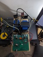
I swapped the output tubes with another set of the same type I had and re-measured.
Socket 1
1= 0
2= 380mv
3= 0
6= 20mv
7= 150mv
8= 0
9= 150mv
Socket 2
1= 0
2= 580mv
3= 0
6= 0
7= 230mv
8=0
9= 230mv
Red/black shows zero DC volts and the red wires bounce between zero and .6vdc. hard to get a solid reading on the red wires.
This explains why there is no voltage reading on pin 6 of the 6922.I do not have the J1 jumper installed
Please connect J1 and measure again.
A total of 6 jumpers? Looks like we found the culprit...I do not have the J1 jumper installed, or any other jumper's
And not shown on the schematic either? Good work Decware. 😀In all fairness to me the instructions didn't say anything about using the jumpers. Gotta figure it out somehow I guess.
jeff
In all fairness to me the instructions didn't say anything about using the jumpers.
If there are no steps to actually install the jumpers, the directions seem more like suggestions.
Unbelievable.
I read all the documentation a few times and didn't come across anything. There's no notes on the schematic and nothing jumped out at me unless others can see something I don't.If there are no steps to actually install the jumpers, the directions seem more like suggestions.
Unbelievable.
I build a pair of Bob Latino M125 monoblocks a couple years ago and had zero problems with those. I thought that this would be way easier to get up and running.
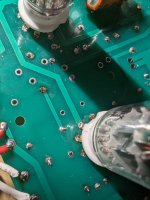
The jumpers are shown on the PCB layout drawing. J1, 2 & 3 are in between the output tubes. J2 & 3 connect the blue OPT leads to the circuit. J4, 5 & 6 are shown at the top and connect the signal inputs.I read all the documentation a few times and didn't come across anything. There's no notes on the schematic and nothing jumped out at me unless others can see something I don't.
So without these jumpers, there will be no signal coming in, and the output transformers will not be connected either.
The fact that this isn't documented and shown on the main schem. is pretty much inexcusable.
jeff
Ok, jumpers
Shall I install all of them? Forgive me for my inexperience, once things go much beyond the instructions I'm clearly out of my depth.
Shall I install all of them? Forgive me for my inexperience, once things go much beyond the instructions I'm clearly out of my depth.
Compare the pcb and the schematic to find out. Probably so, but you have to prove it to yourself.
Unfortunately, even though the jumpers are actually a component, just the same as a resistor,
and have individual reference designators like other components, they are not shown on the schematic.
Unfortunately, even though the jumpers are actually a component, just the same as a resistor,
and have individual reference designators like other components, they are not shown on the schematic.
Roger thatCompare the pcb and the schematic to find out. Probably so, but you have to prove it to yourself.
Unfortunately, even though the jumpers are actually a component, just the same as a resistor,
and have individual reference designators like other components, they are not shown on the schematic.
I'll give it a detailed look tomorrow night.
Thanks everybody
Many boards, audio and elsewhere, have optional jumpers to set gain, etc.
Usually there are instructions for using the jumpers. Not in this case.
Here's an example.
https://www.tubecad.com/2015/04/blog0321.htm
Usually there are instructions for using the jumpers. Not in this case.
Here's an example.
https://www.tubecad.com/2015/04/blog0321.htm
As @vinylkid58 pointed out, the jumpers are shown on the PCB layout drawing. J1, 2 & 3 are in between the output tubes. J2 & 3 connect the blue OPT leads to the circuit. J4, 5 & 6 are shown at the top and connect the signal inputs.
So without these jumpers, there will be no signal coming in, and the output transformers will not be connected either.

Therefore, all jumpers must be installed and can be mounted on the top or bottom of the board.
So without these jumpers, there will be no signal coming in, and the output transformers will not be connected either.
Therefore, all jumpers must be installed and can be mounted on the top or bottom of the board.
Howdy guys
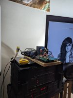
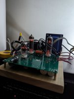
I just wanted to let everyone know I installed all the jumpers this morning and sure enough it works! It sounds great! Just running on a bedroom the imaging is fantastic.
I'd like to thank everyone here for there helpful advice and patience. It's time to finish the second one and make monoblocks and some chassis.
Attachments
- Home
- Amplifiers
- Tubes / Valves
- Decware ZKIT-1 help needed