At this point I would resolder the two filament transformer wires, even though the sockets seem to have 6VAC.
The fact that the input tube has plate voltage, but does not conduct, seems to indicate there is no filament voltage.
The fact that the input tube has plate voltage, but does not conduct, seems to indicate there is no filament voltage.
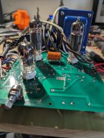
I just noticed that I have these boards populated entirely upside down, including the tube sockets. Would this not change the pinout of the tubes in relation to the board? Am I an idiot?
I figured I'd ask before going to the work of somehow removing those tube sockets and flipping them to the other side.
I figured I'd ask before going to the work of somehow removing those tube sockets and flipping them to the other side.
Attachments


Wait, the parts are on the wrong side of the board?
That won't work since the tube pinouts for the sockets are not symmetric.
Parts with two leads will not be affected.
Check again to be certain the sockets are on the wrong side of the board.
If so, remove them and mount on the correct side.
Volume control as well, since it is not symmetric.
That won't work since the tube pinouts for the sockets are not symmetric.
Parts with two leads will not be affected.
Check again to be certain the sockets are on the wrong side of the board.
If so, remove them and mount on the correct side.
Volume control as well, since it is not symmetric.
Last edited:
So I got that dumb mistake fixed and now all the tubes light up as they should, but test point A has 380VDC and test point B has 415VDC, C measuremes zero volts, D on the 1.5K resistor measures 50 millivolts and the 2.7K resistor measures 4.2V.
Something still seems to be off, but this is an improvement.
Something still seems to be off, but this is an improvement.
Attachments
The exact DC power supply voltages will vary with tubes installed.
Is the volume control on the correct side of the board now?
Does it make sound in the speakers?
Is the volume control on the correct side of the board now?
Does it make sound in the speakers?
I will test when I'm back home this afternoon, I was weary of hooking speakers up yet lol.
I appreciate your help and insight.
I appreciate your help and insight.
Maybe connect a 1k resistor in series with each speaker while testing.
That will be safe, and still loud enough. It just won't sound right.
That will be safe, and still loud enough. It just won't sound right.
That explains why I initially thought you had the PS caps in backwards, because the images you posted didn't match the ones on the Decware site. It was getting late here and I just couldn't get what was going on.I just noticed that I have these boards populated entirely upside down, including the tube sockets
jeff
I hooked the amp up to a set of spare speakers I had but I have no output whatsoever. No hum, no nothing.

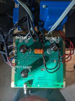
The only number that makes any sense is the #1 pin of the 6922 at 143v. That might actually be close to being right. And there's voltage at the cathode, so that's one triode section functioning. Doesn't appear the other tubes are conducting.
jeff
jeff
I'm going to bring home one of my Fluke meters from work tomorrow, this cheap meter of mine is bouncing all over the place and I can't get a solid reading on the red/black wire. I'll remeasure the tube sockets as well.
Seems to be more than one problem.
The input tube has one section dead, maybe its plate resistor is not connected.
The output tubes are dead, maybe the output transformer has a bad connection.
We know the B+ is there, just too high due to little loading on it.
Probably there is noise on the red/black connection.
The input tube has one section dead, maybe its plate resistor is not connected.
The output tubes are dead, maybe the output transformer has a bad connection.
We know the B+ is there, just too high due to little loading on it.
Probably there is noise on the red/black connection.
- Home
- Amplifiers
- Tubes / Valves
- Decware ZKIT-1 help needed