Just checkong as I tend to associate slew rate with analogue and tend to use 20-80% rise time with digital.
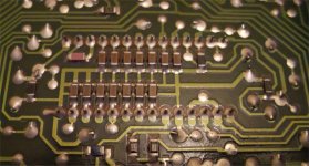
The ground plane is lord of the board🙂
http://www.elmac.co.uk/pdfs/Lord_of_the_board.pdf
In fact a lot of digital boards these days have numerous ground planes, the same ground plane just repeated on multiple layers, and quite often a third of the layers are the ground plane.
The ground plane is lord of the board🙂
http://www.elmac.co.uk/pdfs/Lord_of_the_board.pdf
In fact a lot of digital boards these days have numerous ground planes, the same ground plane just repeated on multiple layers, and quite often a third of the layers are the ground plane.
Hi,
I personally tend to say "all digital signals are analogue"...
Clean grounds are, where conflicting requirements cannot be decomposed into separate solution (e.g. several fully independent floating power supplies like I use for AMR) then as much ground plane as possible reduces the problems much, but it cannot eliminate them.
Just use a fast and sensitive 'scope (like my 150MHz/1mV HP one), attach a short soldered ground probe to the main chip's ground and use the probe to look at just how much voltage with what sort of signal patters can be found in a few inch of "ground"...
So perhaps it is less the "Lord" who rules nobly and directs affairs with dignity, but more like Chinese P.L.A., that attempts with massive pressure to keep everything under control and almost succeeds, except every now and then when the locals have a little bit of a riot....
Ciao T
Just checkong as I tend to associate slew rate with analogue and tend to use 20-80% rise time with digital.
I personally tend to say "all digital signals are analogue"...
The ground plane is lord of the board🙂
Clean grounds are, where conflicting requirements cannot be decomposed into separate solution (e.g. several fully independent floating power supplies like I use for AMR) then as much ground plane as possible reduces the problems much, but it cannot eliminate them.
Just use a fast and sensitive 'scope (like my 150MHz/1mV HP one), attach a short soldered ground probe to the main chip's ground and use the probe to look at just how much voltage with what sort of signal patters can be found in a few inch of "ground"...
So perhaps it is less the "Lord" who rules nobly and directs affairs with dignity, but more like Chinese P.L.A., that attempts with massive pressure to keep everything under control and almost succeeds, except every now and then when the locals have a little bit of a riot....
Ciao T
Btw, the Salas shunts have an output impedance of <5 mOhm up until about 200KHz, after which it shoots up. This makes the Salas shunt alright for the analog supplies, but it doesn't fois r digital... seems another low noise low impedance reg would be better.
The output voltage of a Salas shunt is dependent of the instantaneous VBE of the bjt and it difficult to get really good references with the voltages required.
How about a simple bjt diff pair instead (driving the fet shunt element) with one of the better monolitic references that could also be extensively RC filtered (well atleast before base current becomes a concern..) Collector load could be resistive sacrificing some gain (and thus output impedance) for a wider more constant output impedance.
This wouln't become to complex, maybe shooting for ~20mOhm or thereabouts with very low noise and temperature stability.
Tazzz ... Of what?
?!
I just ment one might be better served by trading excessively low output impedance for impedance flatness over an extended bandwidth.
Of course there will still be a point where the loop gain dropps of and the output impedance rises and capacitors have to take over from then on but its possible to push that point quite high in frequency.
Last edited:
Low noise
Low impedance
Low impedance over large bandwidth
... Is there an ideal solution??
Looking at the datasheet for a tl431 I don't think its all that bad to start with decently flat impedance up to 50Khz and a quoted noise of <60nV/Sqrt(Hz) @ 10Hz.
Hi,
The noise is fine, however I find around 120nV|/Hz in my datasheets (TI) for the TL431 above 100Hz, I estimate around 17uV for an optimised TL431 Shunt.
This can be bettered, however this level of noise contributes around -160dBfs noise, which is safely below the self noise of the TDA1541 at bipolar zero (-110dB).
The impedance is a bit on the high side, with 0.2 Ohm typical, but this impedance is fairly linear, so again not too bad and crucially it stays flat quite high. It is normally easy to parallel a nice set of decoupling cap's with the 431 to have a nice flat impedance curve into the 10's of MHz (this does need SMD Cap's, preferably the X2Y devices which outperform most else)...
Ciao T
Looking at the datasheet for a tl431 I don't think its all that bad to start with decently flat impedance up to 50Khz and a quoted noise of <60nV/Sqrt(Hz) @ 10Hz.
The noise is fine, however I find around 120nV|/Hz in my datasheets (TI) for the TL431 above 100Hz, I estimate around 17uV for an optimised TL431 Shunt.
This can be bettered, however this level of noise contributes around -160dBfs noise, which is safely below the self noise of the TDA1541 at bipolar zero (-110dB).
The impedance is a bit on the high side, with 0.2 Ohm typical, but this impedance is fairly linear, so again not too bad and crucially it stays flat quite high. It is normally easy to parallel a nice set of decoupling cap's with the 431 to have a nice flat impedance curve into the 10's of MHz (this does need SMD Cap's, preferably the X2Y devices which outperform most else)...
Ciao T
Hi,
The noise is fine, however I find around 120nV|/Hz in my datasheets (TI) for the TL431 above 100Hz, I estimate around 17uV for an optimised TL431 Shunt.
This can be bettered, however this level of noise contributes around -160dBfs noise, which is safely below the self noise of the TDA1541 at bipolar zero (-110dB).
The impedance is a bit on the high side, with 0.2 Ohm typical, but this impedance is fairly linear, so again not too bad and crucially it stays flat quite high. It is normally easy to parallel a nice set of decoupling cap's with the 431 to have a nice flat impedance curve into the 10's of MHz (this does need SMD Cap's, preferably the X2Y devices which outperform most else)...
Ciao T
How about letting the TL431 control a PNP shunt element (as in the high current application examples) and restrict its use to being a voltage reference & error amp that way it should be possible to both linearize and lower the output impedance with the addition of just a few components.
Thanks for the tip on the decoupling caps. More pads to solder but with a new PCB I can definitely make use of them especially since they are conveniently available from farnell.
Hi,
It will lower the output impedance, it may further linearise the behaviour, but it uses additional feedback, so it will either not be stable or will have to compensated for a bandwidth that preserves stability.
Now if you worry about the 0.2 Ohm at LF, you can lower that. but you cannot improve the performance where it matters.
You are quite welcome.
Some may think them "bloody expensive voodoo cap's", but try them on a suitable > 100MHz bandwidth analyser.
I guess you could use a bunch of 0402 cap's in parallel, have fun soldering.
Ciao T
How about letting the TL431 control a PNP shunt element (as in the high current application examples) and restrict its use to being a voltage reference & error amp that way it should be possible to both linearize and lower the output impedance with the addition of just a few components.
It will lower the output impedance, it may further linearise the behaviour, but it uses additional feedback, so it will either not be stable or will have to compensated for a bandwidth that preserves stability.
Now if you worry about the 0.2 Ohm at LF, you can lower that. but you cannot improve the performance where it matters.
Thanks for the tip on the decoupling caps. More pads to solder but with a new PCB I can definitely make use of them especially since they are conveniently available from farnell.
You are quite welcome.
Some may think them "bloody expensive voodoo cap's", but try them on a suitable > 100MHz bandwidth analyser.
I guess you could use a bunch of 0402 cap's in parallel, have fun soldering.
Ciao T
Now if you worry about the 0.2 Ohm at LF, you can lower that. but you cannot improve the performance where it matters.
You are referring to degraded dynamical performance cased by reduced stability margins from the added phase shift from the additional stage?
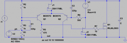
I've attached a draft schematic here of a discrete shunt reg I have not thoroughly optimized it in any way but the general topology gives a wide bandwidth and a very flat output impedance (Which I likely have to degrade in order to get good phase&gain margins).
Attachments
Hi,
Not really. If you lower the impedance of the 431 (for example by adding external transistors) you must lower the bandwidth, TANSTAAFL ...
Well, let me say it like this.
A TL431 and LM334 (or LM317) CCS "SuperShuntReg" can be made using precisely seven parts (CCS Part plus current Set resistor, 431 plus resistive Divider, two Bypass capacitors. It's performance is in many places "good enough" and is brutally simple. It is so small, it can often be retro-fitted to existing gear.
It CAN of course be bettered. By a lot in every area (lower noise, lower Z, wider bandwidth) except cost/complexity. So we need to work out if the improved performance from such much more complex options is beneficial.
Ciao T
You are referring to degraded dynamical performance cased by reduced stability margins from the added phase shift from the additional stage?
Not really. If you lower the impedance of the 431 (for example by adding external transistors) you must lower the bandwidth, TANSTAAFL ...
I've attached a draft schematic here of a discrete shunt reg I have not thoroughly optimized it in any way but the general topology gives a wide bandwidth and a very flat output impedance (Which I likely have to degrade in order to get good phase&gain margins).
Well, let me say it like this.
A TL431 and LM334 (or LM317) CCS "SuperShuntReg" can be made using precisely seven parts (CCS Part plus current Set resistor, 431 plus resistive Divider, two Bypass capacitors. It's performance is in many places "good enough" and is brutally simple. It is so small, it can often be retro-fitted to existing gear.
It CAN of course be bettered. By a lot in every area (lower noise, lower Z, wider bandwidth) except cost/complexity. So we need to work out if the improved performance from such much more complex options is beneficial.
Ciao T
It CAN of course be bettered. By a lot in every area (lower noise, lower Z, wider bandwidth) except cost/complexity. So we need to work out if the improved performance from such much more complex options is beneficial.
Let me elaborate a little about what I want to do. I intend to use two cpld's one to split the data into left and right and one to generate the different clocks needed in the dac from a local masterclock. That way I can use the recievers (likely a cs8416) in slave mode to reduce the frames from 64 to 32bits of course the local masterclock must be in sync so either I'll use a VCXO and a PLL or I feed back a divided down clock to slave either juli@ soundcard or a cd player.
I also need an MCU to do some householding tasks like applying mute when needed, determine sample rate to select the right clock implement a dpll and rescale the DEM (by controlling the cpld) for different sample rates and so on.
Since I won't be driving the cpld's to very high frequencies they won't draw much current so I was thinking I use a TL431 to generate the voltage for the logic drivers (2.5V and/or 3.3V they will need to do some translating) and use an LDO down from that to feed the core. LP5900 from national seems like a nice choice for the 1.8V LDO.
For the oscillators something really low noise like something based on : Ultra-Low-Noise LDO Achieves 6nV/√Hz Noise Performance - Maxim
For the rest of the digital side the mcu the recievers and the line drivers TL431 seems appropriate.
That leaves the TDA1541 its associated parts and the I/V there I think some added complexity can be justified as long as it doesn't go totally overboard as I still need to solder it together 😛
....implement a dpll .....
For the oscillators something really low noise like something based on : Ultra-Low-Noise LDO Achieves 6nV/√Hz Noise Performance - Maxim
Found that link too when i was looking for a low noise psu. Also use something like this for the DACs generating the control voltage for the VCXOs.
Hi,
I would probably not put too much effort into the CPLD supplies. These buggers are so noisy anyway that you need to reclock after them. Often latched are integrated and then you need to only watch the clock routing and I/O Supplies. So I'd probably only bother with 431 on the I/O Supplies and only if I do not apply reclocking directly at the DAC, which I invariably do on my own designs (together with RF relays to switch the clocks for these and striplines to carry the clock)...
You can get better noise performance from an LM329 and an NE5534.
I think the 431 is fine for the 1541, as long as you get the circuit design and layout right. But no-one stops you from using more sophisticated regulators.
Ciao T
Since I won't be driving the cpld's to very high frequencies they won't draw much current so I was thinking I use a TL431 to generate the voltage for the logic drivers (2.5V and/or 3.3V they will need to do some translating) and use an LDO down from that to feed the core. LP5900 from national seems like a nice choice for the 1.8V LDO.
I would probably not put too much effort into the CPLD supplies. These buggers are so noisy anyway that you need to reclock after them. Often latched are integrated and then you need to only watch the clock routing and I/O Supplies. So I'd probably only bother with 431 on the I/O Supplies and only if I do not apply reclocking directly at the DAC, which I invariably do on my own designs (together with RF relays to switch the clocks for these and striplines to carry the clock)...
For the oscillators something really low noise like something based on : Ultra-Low-Noise LDO Achieves 6nV/√Hz Noise Performance - Maxim
You can get better noise performance from an LM329 and an NE5534.
That leaves the TDA1541 its associated parts and the I/V there I think some added complexity can be justified as long as it doesn't go totally overboard as I still need to solder it together 😛
I think the 431 is fine for the 1541, as long as you get the circuit design and layout right. But no-one stops you from using more sophisticated regulators.
Ciao T
better decoupling due to the lower inductance of all respective current loops. Thorstens' advise is correct.
best
Sorry for the OT interruption everyone, but I haven't been able to get a response to multiple direct inquiries. Hate to have to air this here.
Guido,
I see you have time to participate in forum discussions. Maybe you have time to ship out that order you promised a few weeks ago? Or at least take the few seconds it takes to respond to status inquiries?
Sheldon
You can get better noise performance from an LM329 and an NE5534.
I'm aware of the LM329 buried zener reference but its 6.9V is somewhat unconvenient. Linear have a pretty new reference LTC6655 that is available in different voltages and has very low noise.
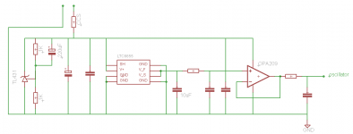
I'm thinking a TL431 set to 5V as a prereg followed by an LTC6655 and an OPA209. This could give a decently small low noise supply.
I have attached a schematic here.
Attachments
Found that link too when i was looking for a low noise psu. Also use something like this for the DACs generating the control voltage for the VCXOs.
Yes, I'm going to feed it from the same supply as the oscillators and maybe use ac coupled spi instead of i2c (that requires pull-ups) to further isolate it from the MCU.
I think also any circuitry that handles the masterclock (reclockers) should get an equally clean supply to ensure low phase noise. Especially considering the epically low jitter levels of new oscillators such as the CCHD-957 from crystek.
Hi,
Why? Divide it down to 5V (or even 3.3V) and use the divider as first part of the filter. It is a long established part and very easy to find.
Noise is comparable to LM329 divided to the Voltage.
The shunt before all of this is not really that useful. Use an optimised LM317 as pre-reg, throw in some chokes.
I would probably stick to "old faithful" LM317, LM329 and NE5534 for the job, the results are bound to be within "experimental error" compared to the new stuff, they are easier DIY'ed as they are all TO-92, DIP etc.
Nothing wrong with the new chips of course...
Have fun.
Ciao T
I'm aware of the LM329 buried zener reference but its 6.9V is somewhat unconvenient.
Why? Divide it down to 5V (or even 3.3V) and use the divider as first part of the filter. It is a long established part and very easy to find.
Linear have a pretty new reference LTC6655 that is available in different voltages and has very low noise.
Noise is comparable to LM329 divided to the Voltage.
I'm thinking a TL431 set to 5V as a prereg followed by an LTC6655 and an OPA209. This could give a decently small low noise supply.
The shunt before all of this is not really that useful. Use an optimised LM317 as pre-reg, throw in some chokes.
I would probably stick to "old faithful" LM317, LM329 and NE5534 for the job, the results are bound to be within "experimental error" compared to the new stuff, they are easier DIY'ed as they are all TO-92, DIP etc.
Nothing wrong with the new chips of course...
Have fun.
Ciao T
- Status
- Not open for further replies.
- Home
- Source & Line
- Digital Source
- decoupling TDA1541A