Hi,
The Salas shunt should have less dynamic impedance in the audio range and less noise. It seems pointless to follow it with a 431. Did you use a CCS for the 431?
Usually the 431 plus IC CCS makes for a simple, compact solution that is often "good enough". It can be improved upon, but not without substantial complexity, plus it is already better than 3 Terminal regulators.
Ciao T
Makes sense...
Btw, the Salas shunts have an output impedance of <5 mOhm up until about 200KHz, after which it shoots up. This makes the Salas shunt alright for the analog supplies, but it doesn't for digital... seems another low noise low impedance reg would be better.
What are the stats for the tl431?
@ batteryman, I'm not knowledgeable enough so I just picked up Pedja's schem 🙂
Studiostevus, can you elaborate more on Salas output impedance ?, again I'm blind here and noticed that Salas reg last capacitor plus its bypass cap values and brands are highly sensitive for sound quality. Not so with the rest of regs caps. Thanks
Studiostevus, can you elaborate more on Salas output impedance ?, again I'm blind here and noticed that Salas reg last capacitor plus its bypass cap values and brands are highly sensitive for sound quality. Not so with the rest of regs caps. Thanks
Hi Tazzz,
IMO only NXP (Philips) HEF4517 can operate easily with +5V in such speed. Yes, it can work only <48K sampling, but if you want more, you can increase power voltage up to +15V. This theoreticaly should allow to operate <150K, 96K easily, but then will be a need to tune up input and output levels...
P.S. If someone needs HEF4517B please PM - I bought them last year from Farnell - smallest available package, still to much for me 🙂
I am aware of that possibility but IMHO its better to go for a cpld especially since I would be making a new PCB anyway.
Are you going to use upsampling to 192k, or you have digital source with such sampling rate?
For the moment I see reason only for 96k (for example output of Behringer SCR2496 after upsampling).
Or you going to split oversampled data from SAA7220?
No at least not initially. But I want the dac to accept most any digital source and have multiple inputs. This is a convenience feature. But this is causing some grief not only with how the data is split up into left and right but also with regard to clock generation. At this point I'm thinking one small cpld configured as a synchronous counter with internally muxed outputs for BCLK, DEM and WCLK so these are rescaled correctly for different samplerates and another larger cpld for splitting the data into left and right and also reducing the frame length from 64fs to 32fs.
But I will also need to decide how to handle the need of dither for >16bit material it could be done in the analogue domain...
Hello, I've been enjoying what passes as a summer holiday in this part of the world, and trying to finish my speakers while its not raining! Sunny UK west pennines.
The reason why I said an interlectual exercise is that as Thorsten and othners have pointed out is the complexity of the supplies, which both intriges and confuses me somewhat. Plus I will probably never get around to building it myself.
What I had in mind is pretty much like Tazzz's layout, with 1206 SMD caps under the TDA, I would move them away from the PTH pins slightly to avoid solder thieving, though with manual assembly it may not be so bad. I would also use SMD for the supply decoupling. But that layout seems to pretty much cover the general views. The only thing different I would do is route the digital signals down the middle of the TDA on the top layer so they are referenced to the digital ground and a true microstrip lines (ie running over there respective ground plane on an outer plane), just a minor change but would improve the digital lines signal integrity. You coule then move the decouplers referenced to ground nearer th pins.
Which brings us to the question, do we add a decoupler between the -15 and -5 as I believe it was stated that there is a current flow between them.
Hi,
How is it going. I hear "London's Burning" is back on the Telly, three nights running, with spinoff's for Liverpool, Manchester and Birmingham, I'm totally gobsmacked with this programming (for non UK-People, London's Burning was a TV series about fire fighters in London).
First, if you look closely, all signal pins are next to each other and the digital ground pin.This makes it easy routing signal lines and grounds there.
I would STRONGLY suggest you design in a reclocker for BCK, WCK and Data and John Browns DEM Reclocking. With the I2S attenuators and the reclocker very close to the TDA1541 we do not need worry about striplines here, but reserve the stripline for the clock to the reclocker and for the signals to the reclocker...
I would power the reclocker separatly, the I2S attenuators will cause significant local currents, so layout needs some care in other ways.
I think you are still not quite asking the right question here. Think a bit more...
Ciao T
Hello, I've been enjoying what passes as a summer holiday in this part of the world, and trying to finish my speakers while its not raining! Sunny UK west pennines.
How is it going. I hear "London's Burning" is back on the Telly, three nights running, with spinoff's for Liverpool, Manchester and Birmingham, I'm totally gobsmacked with this programming (for non UK-People, London's Burning was a TV series about fire fighters in London).
The only thing different I would do is route the digital signals down the middle of the TDA on the top layer so they are referenced to the digital ground and a true microstrip lines (ie running over there respective ground plane on an outer plane)
First, if you look closely, all signal pins are next to each other and the digital ground pin.This makes it easy routing signal lines and grounds there.
I would STRONGLY suggest you design in a reclocker for BCK, WCK and Data and John Browns DEM Reclocking. With the I2S attenuators and the reclocker very close to the TDA1541 we do not need worry about striplines here, but reserve the stripline for the clock to the reclocker and for the signals to the reclocker...
I would power the reclocker separatly, the I2S attenuators will cause significant local currents, so layout needs some care in other ways.
Which brings us to the question, do we add a decoupler between the -15 and -5 as I believe it was stated that there is a current flow between them.
I think you are still not quite asking the right question here. Think a bit more...
Ciao T
Let me give it a shot... as you see I have yellowed-out parts of the circuit, these are the clock and reclocker (on the top layer). Reason is that this is John Brown's design, and he has shared the schematics but his dac design he uses commercially so I didnt want to reveal exactly how I have placed everything (John, if you read this and find it still inappropriate, please let me know and I remove it).
Soooo... what have I done:
Top layer (in RED):
-clock
-i2s attenuator
-i2s reclocker
-dem reclocker
-tda chip + decoupling
-analog ground plane
Bottom layer (in BLUE)
-digital ground plane
-decoupling of the reclocker flipflops
Yes, it's a bit of spaghetti, I am not a professional layouter and it shows. But... I have never really understood that it needs to look pretty to sound good. To me, it makes more sense to have short clock lines and components placed where they logically should be placed, than to line up resistors neatly and have longer clock lines....

Soooo... what have I done:
Top layer (in RED):
-clock
-i2s attenuator
-i2s reclocker
-dem reclocker
-tda chip + decoupling
-analog ground plane
Bottom layer (in BLUE)
-digital ground plane
-decoupling of the reclocker flipflops
Yes, it's a bit of spaghetti, I am not a professional layouter and it shows.
But... I have never really understood that it needs to look pretty to sound good. To me, it makes more sense to have short clock lines and components placed where they logically should be placed, than to line up resistors neatly and have longer clock lines....Hi,
I would suggest placing the DEM Decoupling Cap's vertical and keep them all inside the TDA1541 pins...
Ciao T
Let me give it a shot... as you see I have yellowed-out parts of the circuit, these are the clock and reclocker (on the top layer). Reason is that this is John Brown's design, and he has shared the schematics but his dac design he uses commercially so I didnt want to reveal exactly how I have placed everything (John, if you read this and find it still inappropriate, please let me know and I remove it).
I would suggest placing the DEM Decoupling Cap's vertical and keep them all inside the TDA1541 pins...
Ciao T
Pourquoi? The 1210's don't fit next to one another, so i thought this would be a good solution. What does putting them all inside the tda footprint give?
Hi,
They fit if you stand them on side, which also reduces inductance.
Fitting them inside reduces inductance...
Ciao T
Pourquoi? The 1210's don't fit next to one another, so i thought this would be a good solution. What does putting them all inside the tda footprint give?
They fit if you stand them on side, which also reduces inductance.
Fitting them inside reduces inductance...
Ciao T
I would STRONGLY suggest you design in a reclocker for BCK, WCK and Data and John Browns DEM Reclocking. With the I2S attenuators and the reclocker very close to the TDA1541 we do not need worry about striplines here, but reserve the stripline for the clock to the reclocker and for the signals to the reclocker...
Would you still see an advantage by reclocking close to the dac in such case the needed clocks (bclk, wckl and dem) are generated from a synchronous divider and fed back to the i2s datasource? I think such a solution can be kept very clean it would even be possible to not divide bclk at all.
But why would it matter if data wclk and bclk are a bit off as long as not horrendously so? Since ideally no digital input to the dac should change state for half a bclk clockcycle before the dac latches (in time multiplexed mode Is this not enough time for anything injected by capacitive coupling from the inputs switching to the dac substrate to die out?
Pourquoi? The 1210's don't fit next to one another, so i thought this would be a good solution. What does putting them all inside the tda footprint give?
better decoupling due to the lower inductance of all respective current loops. Thorstens' advise is correct.
best
Hi,
Probably yes. The reclocker also acts as driver for I2S attenuators. Keeping all this very local and highly optimised for short loops is likely "a good thing".
Ciao T
Would you still see an advantage by reclocking close to the dac in such case the needed clocks (bclk, wckl and dem) are generated from a synchronous divider and fed back to the i2s datasource?
Probably yes. The reclocker also acts as driver for I2S attenuators. Keeping all this very local and highly optimised for short loops is likely "a good thing".
Ciao T
Regarding those i2s level/slew rate limiters. I looked at the solution posted by ecdesign but I did not quite like it.
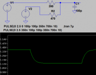
I have posted this solution for consideration it allows the high and low level to be set quite freely as well as giving a more predictable output impedance (usefull for improving source termination of transmission lines altough this should not be strictly necessary for short traces and slow rise times) and the slew rate limit can be easily set by C.
Opinions?
Attachments
Hi,
They do have a distinct advantage insofar that they actually work.
Based on my work on the same subject and the resulting experiences, it does not seem a good idea, but by all means try it...
Ciao T
Regarding those i2s level/slew rate limiters. I looked at the solution posted by ecdesign but I did not quite like it.
They do have a distinct advantage insofar that they actually work.
I have posted this solution for consideration it allows the high and low level to be set quite freely as well as giving a more predictable output impedance (usefull for improving source termination of transmission lines altough this should not be strictly necessary for short traces and slow rise times) and the slew rate limit can be easily set by C.
Opinions?
Based on my work on the same subject and the resulting experiences, it does not seem a good idea, but by all means try it...
Ciao T
By slew rate are we refering I presume to rise time?
My concern with Tazzz option is that most PCB traces are in the region of 70-50 ohm charecteristic impedance (with a ground plane), those resistore are way above what the line impedance is and are going to cause more of a mismatch.
Again a terminology question the I2S attenuaters are level shifters yes?
Hi,
It is the same thing.
I would not fit the I2S attenuators after long trace, not just because of reflections, they will cause additional current flow in the loop back to the source...
I shall repeat my considered recommendation (and will not say any more afterwards)...
1) Fit the I2S attenuators as close to the TDA1541 input pins as possible, use appropriate size SMD parts. Use ECDesigns scheme, it works.
2) Place directly next to the I2S attenuators a reclocker, there is a tradeoff here between using a multiple Flip Flop on a chip part (single clock load but more potential for crossmodulation) and multiple flipflops (more clock loads, less crosstalk).
3) As the reclocker is also the "driver for the I2S attenuators, give it a completely separate local shunt regulates supply, this keeps any circulating currents in the local loop and out of the groundplane.
Kind of.
We are interfacing non-standard ECL logic with TTL Levels.
The inputs on the TDA are able to handle the 0/5V range but they are overdriven if this is used.
They use a PNP (which in 1980's silicone was not that fast - hence the risetime limiter) differential with a CCS tail, with one base tied to two diodes and the other to the input.
You can work it out from there...
Ciao T
By slew rate are we refering I presume to rise time?
It is the same thing.
My concern with Tazzz option is that most PCB traces are in the region of 70-50 ohm charecteristic impedance (with a ground plane), those resistore are way above what the line impedance is and are going to cause more of a mismatch.
I would not fit the I2S attenuators after long trace, not just because of reflections, they will cause additional current flow in the loop back to the source...
I shall repeat my considered recommendation (and will not say any more afterwards)...
1) Fit the I2S attenuators as close to the TDA1541 input pins as possible, use appropriate size SMD parts. Use ECDesigns scheme, it works.
2) Place directly next to the I2S attenuators a reclocker, there is a tradeoff here between using a multiple Flip Flop on a chip part (single clock load but more potential for crossmodulation) and multiple flipflops (more clock loads, less crosstalk).
3) As the reclocker is also the "driver for the I2S attenuators, give it a completely separate local shunt regulates supply, this keeps any circulating currents in the local loop and out of the groundplane.
Again a terminology question the I2S attenuaters are level shifters yes?
Kind of.
We are interfacing non-standard ECL logic with TTL Levels.
The inputs on the TDA are able to handle the 0/5V range but they are overdriven if this is used.
They use a PNP (which in 1980's silicone was not that fast - hence the risetime limiter) differential with a CCS tail, with one base tied to two diodes and the other to the input.
You can work it out from there...
Ciao T
My concern with Tazzz option is that most PCB traces are in the region of 70-50 ohm charecteristic impedance (with a ground plane), those resistore are way above what the line impedance is and are going to cause more of a mismatch.
Yes, but I intended the values as shown to be merely illustrative and the circuit to spur discussion. The capacitor would muck things up as well. Placing it close to the driver would mess with source termination and placing it close to the dac would increase the loop currents. (flowing in the groundplane)
They do have a distinct advantage insofar that they actually work.
I do not doubt ECDesigns solution works but as shown but it only limits voltage swing by the clamping voltages of the diodes and if we go by Htp:s comment voltage swing could be limited even more.
I'm also pretty sure we don't have to worry much about transmission line effects here anyway. ( I specifically mean between the i2s attenuator and the TDA or in the generalized sense any case where the wavelength is long compared to trace length and the slewrate is slow) Between the masterclock and its consumer is another matter. I only mentioned it because I've made a habit of making sure any digital trace which changes state a lot is properly terminated.
I would not fit the I2S attenuators after long trace, not just because of reflections, they will cause additional current flow in the loop back to the source...
I shall repeat my considered recommendation (and will not say any more afterwards)...
1) Fit the I2S attenuators as close to the TDA1541 input pins as possible, use appropriate size SMD parts. Use ECDesigns scheme, it works.
2) Place directly next to the I2S attenuators a reclocker, there is a tradeoff here between using a multiple Flip Flop on a chip part (single clock load but more potential for crossmodulation) and multiple flipflops (more clock loads, less crosstalk).
3) As the reclocker is also the "driver for the I2S attenuators, give it a completely separate local shunt regulates supply, this keeps any circulating currents in the local loop and out of the groundplane.
As I interpret this and what you have previously written in this thread the reoccurring theme is actually keeping return current off the groundplane at all costs and minimizing the impact of those current flowing there anyway.
Come to think about it this is very sensible especially as we have reduced the signal levels. Any potential difference in the groundplane between the TDA and the level limiter would be added as an error voltage to the input the TDA sees... (jitter anyone) Hence placing them close and powering them separately is and advantage.
Also an extremely quiet ground plane can only be beneficial on the analog side as well.
Hi,
What you refer to is a later solution. I was referring to the purely resistive one.
BTW, the TDA1541 can run quite hot and the "reference voltage" of the differential pair input has a one PN Junction tempco, so if you minimise the voltage swing, you need to compensate the tempco...
Agreed.
Essentially, yes. Any large circulating currents (which may be more than just the supply decoupling) and currents always "circulate", should be contained in the shortest possible loop and not use the ground plane any more than unavoidable.
In my view, ideally the ground plane only carries signal return currents and minimal error currents that cannot be completely eliminated and DC.
Digital too. Check Meitners AES Paper on Logic Induced Modulation (LIM)...
The Pin Layout for modern SMD IC's often makes this job a lot easier...
If we combine this with a 4-Layer approach with groundplane (same plane as IC), signal routing plane and power planes) it is possible to make very complex and very quiet designs...
Ciao T
I do not doubt ECDesigns solution works but as shown but it only limits voltage swing by the clamping voltages of the diodes and if we go by Htp:s comment voltage swing could be limited even more.
What you refer to is a later solution. I was referring to the purely resistive one.
BTW, the TDA1541 can run quite hot and the "reference voltage" of the differential pair input has a one PN Junction tempco, so if you minimise the voltage swing, you need to compensate the tempco...
I'm also pretty sure we don't have to worry much about transmission line effects here anyway. ( I specifically mean between the i2s attenuator and the TDA or in the generalized sense any case where the wavelength is long compared to trace length and the slewrate is slow) Between the masterclock and its consumer is another matter.
Agreed.
As I interpret this and what you have previously written in this thread the reoccurring theme is actually keeping return current off the groundplane at all costs and minimizing the impact of those current flowing there anyway.
Essentially, yes. Any large circulating currents (which may be more than just the supply decoupling) and currents always "circulate", should be contained in the shortest possible loop and not use the ground plane any more than unavoidable.
In my view, ideally the ground plane only carries signal return currents and minimal error currents that cannot be completely eliminated and DC.
Also an extremely quiet ground plane can only be beneficial on the analog side as well.
Digital too. Check Meitners AES Paper on Logic Induced Modulation (LIM)...
The Pin Layout for modern SMD IC's often makes this job a lot easier...
If we combine this with a 4-Layer approach with groundplane (same plane as IC), signal routing plane and power planes) it is possible to make very complex and very quiet designs...
Ciao T
- Status
- Not open for further replies.
- Home
- Source & Line
- Digital Source
- decoupling TDA1541A