Hi all,
I've got a class D amplifier that runs in either single ended or bridged configurations, and I'm working to figure out how much decoupling capacitors I need.
The power supply has two rails, -60, gnd, and +60.
There are multiple class D modules on these rails, and they are running at +-15V max signal output when in single ended mode.
In bridged mode, they are running at the full voltage for 70V commercial distributed audio output.
I'm trying to wrap my head around how much decoupling capacitance is needed for my application.
Is it really just a matter of target THD since I'm barely pumping the rails in single ended mode? or is there a safety issue with skimping on decoupling capacitors?
Thanks in advance,
bob
Hi Bob,
If you look at the information you give us, can you estimate a maximum current consumption from the two rails?
Can you conclude what is the energy source feeding the supply rails?
Can you conclude if the more amplifiers are synchronized in a manner that one amplifier carrier is in phase or counter-phase with another amplifier carrier?
I understand your confusion with such a difficult estimation. For sure it is no simple calculation.
It is difficult for you but impossible for us with the present information.
Please give us a maximum power consumption for the whole lot of amplifiers, information about if the rail source is a transformer (60Hz I assume) or an SMPS and how critical a sound artifacts during operation is.
We may be able to help you with a guess on your needs.
First, why are the supply rails so high relative to the output signal amplitude? If possible, you should lower them.
Your question is not so simple to answer without you providing more information. However, this usually boils down to two issues. Amplifier/or regulator stability, and power supply noise rejection. There is more to this than is accurately provided in a simple answer. In essence, you want, of course, the supply rails to remain D.C. stable and A.C. noise/harmonic free. The minimum value of capacitance required to achieved that depends on the peak current draw, and the power supply rejection ratio of the amplifier(s). Remember, the amplifier(s) is undesirably modulating the supply rails. Since signal based current draw is A.C., the rising A.C. impedance (inductance) of the typical electrolytic capacitor in particular is also a factor, particularly for class-D. All that said, capacitance overkill on the supply rails is usually okay, as can be observed from the widespread practice in high-end gear. A notable exception is at the ouput of some voltage regulators, where too much capacitance can produce instability.
Your question is not so simple to answer without you providing more information. However, this usually boils down to two issues. Amplifier/or regulator stability, and power supply noise rejection. There is more to this than is accurately provided in a simple answer. In essence, you want, of course, the supply rails to remain D.C. stable and A.C. noise/harmonic free. The minimum value of capacitance required to achieved that depends on the peak current draw, and the power supply rejection ratio of the amplifier(s). Remember, the amplifier(s) is undesirably modulating the supply rails. Since signal based current draw is A.C., the rising A.C. impedance (inductance) of the typical electrolytic capacitor in particular is also a factor, particularly for class-D. All that said, capacitance overkill on the supply rails is usually okay, as can be observed from the widespread practice in high-end gear. A notable exception is at the ouput of some voltage regulators, where too much capacitance can produce instability.
Last edited:
The relation is quite straightforward to derive.
dV is the peak to peak ripple voltage.
Please note, in reality the voltage ripple will be slightly lower depending on circuit conditions.
Code:
For any capacitor:
Q = CV

Differentiating: dQ = C.dV

Assuming full wave rectification at frequency f and load current I.

dQ = I.dT  (I is current, dT is time interval between rectified voltage peaks)

=> dQ = I.1/(2f)

Substituting in the first equation in differential form:

I/(2f) = C.dV

Rearranging:

dV = I / {2fC}Please note, in reality the voltage ripple will be slightly lower depending on circuit conditions.
Last edited:
Hi guys,
I'd say that truth is not (never?) so simple...
Edbarx, your maths are correct, but the model they are derived from is fairly away to the one initially described and one will end-up with surprisingly small caps when feeding it with actual figures.
Sizing the caps actually must address two concerns here:
1/what size sufficiently filters-out the 100Hz (or 120Hz) ripple for it to be not heard -and you must define a max-ripple target value here-
2/what size and also, what type and how many caps are needed to prevent your amplifiers to "modulate" the DC rail voltages so that the signal passing through them does not self-distort because of the apparent rail impedance.
Computations for this will need you to cut some corners and state some worst case values to make it all easier to compute and not un-necessary complicated.
For 1/ you need bulk alcaps that will be your energy storage feeding your amps when the head full-wave rectifier is fully OFF -i.e. when caps voltage is lower than your transformer secondary voltage; this usually lasts for about70% of time on a switching PSU, but here you will be aiming for a smaller ripple... that you will never get close to if you do not use a post-regulator (switching buck is the way to go here).
For 2/ you need to assess what will be the largest rms current drawn by your several amplifiers at the worst case, so you will be able to:
-choose a low ESR alcap and put enough in parallel to reach a total ESR of some mOhms.
-define how many you must wire in parallel to cope with computed high-frequency RMS current so that they do not dry-out and fail within a year or less...(you may aim for at least a couple of years full load, which will actually be spread over 10 years normal listening...)
-pay attention to the wiring, which at this stage is NOT a straigh-forward task if you do not want to ruin the nice DC rail decoupling that you just designed.
You could see that this is not an easy task, as FauxFrench correctly pointed.
In practice, any dirty and wrong computations could give you a nowhere-near result and seem to work...for a while or without electrical measurements on actual results.
If one wants to tacke it from top to bottom, better get some help from an electronics engineer, but you could get to something efficient just with following the main guidelines.
Hope this helps (and perhaps recall some courses from highschool to some readers)
Kal.
Hi all,
Thank you so much for your input. I'll try to add more info here:
Maximum current delivered by the rails is 9A, from either -60V or +60V rail. I believe that half of the modules will pump one rail in SE mode, and the other half will pump the other rail.
Each SE channel is limited to 75W and there are up to 12 channels in SE mode. In bridged mode, the channels could conceivably draw much more, but are automatically limited as a group by a host controller that prevents PSU overlimit.
The signals on the SE mode channels will not be synchronized under any circumstance.
The power supply (SMPS with PWM @ 100kHz and PFC at 90kHz) has ripple and noise of 200mVP-P measured at 20MHz bandwidth using 12" twisted pair-wire terminated with 0.1uF and 47uF capacitors in parallel. Rated PSU efficiency is 94%, and the power factor is >0.98 at full load on 115VAC.
@Ken Newton - the rails are so high because they need to be at least that high to support 70V transformerless output mode.
@Kalamin - can you suggest a starting point for max-ripple if the bridged module should be able to draw 150W at 0.1% HD due to ripple (70V RMS into high impedance load)?
I apologize if the formulas have already been provided here in the messages, but this is new territory for me, and I'm still on the very early stages of the learning curve.
Thanks again,
Bob
EDIT: I'd like to reiterate this question: Is it really just a matter of target THD since I'm barely pumping the rails in single ended mode? or is there a safety issue with skimping on decoupling capacitors?
Hi all,
The signals on the SE mode channels will not be synchronized under any circumstance.
By signals, do you refer to the switching clocks? Ideally, you want the switching to either be synchronized, or to be far enough apart in frequency so as not to potentially produce audio band inter-modulation products. Especially, if you have multiple amplifier modules share any power rails. However, unless your modules support implementation of such synchronization, you will simply have to accept that potential. You may not hear it if even should it occur anyhow. However,mthis does further highlight the need to effectively clean the supply rails of harmonics.
EDIT: I'd like to reiterate this question: Is it really just a matter of target THD since I'm barely pumping the rails in single ended mode? or is there a safety issue with skimping on decoupling capacitors?
What particular safety issue are you referring to?
However, unless your modules support implementation of such synchronization, you will simply have to accept that potential
I'm afraid this is right. As a designer of such a system, you never know what the user may ending doing with it, so to stay on the safe side, just consider all amps on a rail run in parallel with same signal at full power.
The power supply (SMPS with PWM @ 100kHz and PFC at 90kHz) has ripple and noise of 200mVP-P measured at 20MHz bandwidth using 12" twisted pair-wire terminated with 0.1uF and 47uF capacitors in parallel. Rated PSU efficiency is 94%, and the power factor is >0.98 at full load on 115VAC.
That's a good and sensible starting point, so your rails are stable (regulated) from DC up to several kHz thanks to the control loop of the switching PSU. Your PSU looks like it is an LLC resonance switching PSU, with typically negligible 60Hz output ripple.
Even if there was some audio-freq. ripple, the amount of it at the amplifiers' output would obviously depend on its PSRR, which may push this item sufficiently down on the THD-cause list (i.e. 60dB attenuation on 200mV rail ripple, "injected" to a several Vrms output signal is not something to think about IMHO... )
@Kalamin - can you suggest a starting point for max-ripple if the bridged module should be able to draw 150W at 0.1% HD due to ripple (70V RMS into high impedance load)?
I couldn't figure out computing this, due to the fact that starting from a desired THD at the output of an amplifier and making the assumption this low value would be only caused by DC rails ripple would take us nowhere for 2 reasons:
-obviously, there are several other causes for THD to reach 0.1% without even mentioning DC rail ripple and
-trying assessing it seems out of realistic reach to me: OutputTHD=f(DCrailRipple) function has too many unknown parameters for us to implement something and hope it will be efficient.
I think I'd pick up a couple of major TDH causes first and apply good practice to ensure no loose ends, but you may already have done it?
What I could help on is: what is the rms current your system is drawing from your amplifiers' alcaps (not from your PSU, likely being too "far" away @ switching freq. of amplifiers, due to the wiring) and is it all OK for a long-lasting operation?
BTW, I'm using a TPA3255-based class D amplifier, fed by a switching PSU just like yours. Though I confess I never hooked an audio-analyser at it, my opinion is that its output THD doesn't count the PSU's 50Hz ripple (I'm in france...) among its 5 first causes or more...
Otherwise said: using a supply which has inherently no 50-60Hz output ripple keeps you away from worrying about it.
Regards,
Kal
Ten thousand microfarads per ampere of worst case (maximum) current drawn from the supply. Run it through edbarx's formulae and you'll find that's 1.0 volt peak-to-trough of ripple in the worst case.
So for a power supply that drives two channels, each channel delivering 100 watts RMS to a 4 ohm load, that's 71,000 microfarads on the Vpos rail and 71,000 microfarads on the Vneg rail. 100 watts RMS per channel into 8 ohms, you say? --> 50,000 microfarads on each rail.
_
So for a power supply that drives two channels, each channel delivering 100 watts RMS to a 4 ohm load, that's 71,000 microfarads on the Vpos rail and 71,000 microfarads on the Vneg rail. 100 watts RMS per channel into 8 ohms, you say? --> 50,000 microfarads on each rail.
_
Last edited:
Hi Mark,
true: 1A drawn from a 10000µF cap for 10ms gives a 1V voltage drop, but your system never does this from the PSU output...such case is close to -but overkill- what is happening between the PSU's input bridge rectifier and the primary-side high-voltage bulk caps of the PSU, where current lumps are drawn from the Mains at each semi-cycle.
The Mains frequency (10ms semi-cycle) has here no relevance with the PSU output voltage, so your 10000µF cap never has a 10ms "window" where it must supply the amplifier without power coming from the PSU output... Do you follow me?
The thing is: PSU feeds DC current to its output caps and maintains the output voltage through its feedback loop; at the same time, the class D amplifier draws high freq. current (PWM square-waves) from its own alcaps (local on board), which take the corresponding rms current and draw re-fill from the PSU at lower frequency (LP'ed audio message):
A well designed system would be that current flowing from PSU output to the Class D amplifier is only DC + some LF variations, all high freq. content being swallowed by the on-board alcaps of the amplifier, where wiring is shortest w.r.t. the power transistors location and therefore current could reach high di/dt rates for best performance.
I think when we are talking about 100/120 Hz ripple - it is not about decoupling but it is about filtering.Sizing the caps actually must address two concerns here:
1/what size sufficiently filters-out the 100Hz (or 120Hz) ripple for it to be not heard
Decoupling - it is when we are talking about how to get rid of power lines inductive type impedance (that means much higher frequencies).
Yes, there is a difference between these two terminologies:
-filtering= you are interested by the frequency content of the electric signal of concern: i.e. you design a "filter"
-decoupling: what you try to achieve here is to get the two nodes of concern to be the same potential for AC signals. i.e. +V and Ground always are supposed to be shorted for AC signals.
well, just vocabulary...
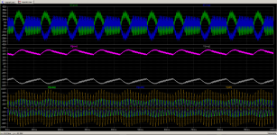
If in doubt throw LTSpice at it. For the moment ignoring the fact that these amplifiers are being supplied by an SMPS start off assuming lump of iron and bridge rectified supplies. Mess about with the attached model and measure ripple current in the capacitors to get the feel of things. Copy and paste the Class D sections to suit your configuration mix. Adjust signal levels for output conditions. Later you can add some approximation of the SMPS but that will very much depend on the nature of the beast.
...
...
Attachments

- Home
- Amplifiers
- Power Supplies
- Decoupling Capacitor Calculations?