Hello from Switzerland, 
This is my first post on the forum so I hope that I'm on the right forum (if not please redirect me to right place) and that I'll be able to provide all the information you need to help me fix the problem I'm facing.
The issue
The context is the following. I own a Linn Sneaky Music DS (first version, the one with no power switch) bought 7 years ago. The device was working perfectly until a few weeks ago (it was on 24/7 as there was no power switch...) Then one day it turned off and never woke up again.
I suspect that the problem comes from the power supply as when I plug the main cable, I can't hear anymore the switching noise I used to hear prior to the issue (a "click" that i could hear when the main cable was plugged into the device. After the click, the led of the device used to turn blue. Now it's just dead).
What I did so far
I went to various shops and to a Linn official retailer, but the all told me that the quote would be 150-300 CHF (~USD), that they don't know if they will be able to repair it, and that probably they will have to send the product back to the UK to have it fixed a the factory...
I also contacted Linn to ask them if hey could provide schematics for the power supply (the product was discontinued 3 years ago), but they refused... they told me to reset the device by pressing a button but it didn't solved the issue.
My request
As I cannot afford spending so much for a hypothetical repair (not to say to buy a new device) my last chance is to try to fix it myself. However I don't really know where to start... It would be great if you could help me.
Here is was I am able to do: discharge capacitors (it can help to stay alive), solder/desolder tht and smd components (i also have a hot air gun station), measure with a DMM.
I will provide pictures of the power supply in a future message (need to reopen the case and it's almost midnight here.) Meantime if you have any tips on where to start it would be great.
Thank you in advance and best regards,
Michel
This has the "Linn Switch Mode Power Supply (SMPS)" so we can assume that is the problem.
Proprietary and not easy to repair, especially without the schematic.
Proprietary and not easy to repair, especially without the schematic.
Open the box and check if there is a fuse for a start.
You said You'd hear a click, or was it a spark ? SMPS's usually emit a spark when connected to mains.
You said You'd hear a click, or was it a spark ? SMPS's usually emit a spark when connected to mains.
Open the box and check if there is a fuse for a start.
You said You'd hear a click, or was it a spark ? SMPS's usually emit a spark when connected to mains.
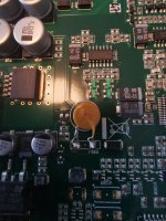
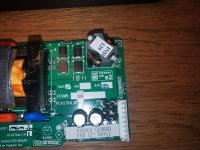
There is a resetable fuse in the middle of the main PCB (see attachment). I found the datasheet of this part here:
https://m.littelfuse.com/~/media/el...ble_ptcs/littelfuse_ptc_72r_datasheet.pdf.pdf
Last time I heard the click was 9 months ago... But it was both, first a spark then a relay like click.
Attachments
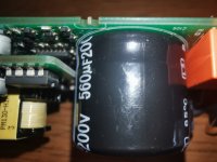
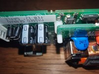
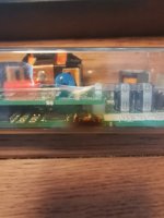
Here are some picture I just took of the power supply board.
On one picture (burn.jpg), I see that something went "hot" (burnt plastic?), but when looking at the PCB itself I can't see anything obvious (no visual sign of something having taken fire, and there was no magic smoke when the device stopped working.)
I also added pictures of top and sides of the PS boards. Maybe you can see something obvious (but I don't.)
I still haven't found how to separate the main power supply PCB from the daughter one (side_4.jpg picture). I tried to pull it but with no success. Should I de-solder the pins ?
Regards,
Attachments
-
 side_5.jpg436 KB · Views: 435
 -
 side_4.jpg438.7 KB · Views: 367
 -
 side_3.jpg428.8 KB · Views: 394
 -
 side_2.jpg386.9 KB · Views: 339
 -
 side_1.jpg405.1 KB · Views: 366
 -
 top_3.jpg569.6 KB · Views: 356
 -
 top_2.jpg625.2 KB · Views: 515
 -
 top_1.jpg668.5 KB · Views: 698
 -
 burn_pcb.jpg444.5 KB · Views: 472
 -
 burn.jpg358.8 KB · Views: 481
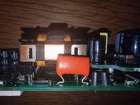
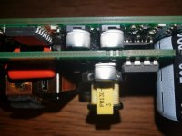
The little piggyback boards seems to be a 24V supply that is stacked on top of a multi output supply because of board space restrictions. The IC next to it is a switcher IC that is pretty straightforward and quite easy to understand.
I googled the part number of the yellow transformer and came up with this datasheet for it. http://www.premiermag.com/pdf/pny-24004.pdf from that i deduced that its likely a +24 or -24V 400mA power supply.
The burnt part of your enclosure seems to line up well with the two SMD electrolytic capacitors under the piggyback. Those somehow look odd to me, if you have a decent multimeter with capacitance measurement mode you may want to solder two pieces of wire to both the terminals and measure them for resistance and capacitance. If you have one of the cheap Chinese component testers/ESR meters at hand you can use that to test them. Good capacitors should increase in resistance value once the multimeter starts charging it.
If that doesnt solve the fault. google every IC you can find on the board, and check the power supply rail impedance. (Ohm meter over the VCC and GND pin) If the IC somehow has a FB or REF pin measure that to the GND pin. If you measure a short or a few houndred ohms report back.
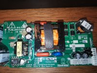
That click you where hearing was likely coming from the Relay on the bottom left corner TOP1.JPG. Its the orange relay. That is likely switched on by a voltage coming from the big transformer, so if the big transformer is not getting any switching signal from the controller there wont be any click from the relay bridging the on board resistor. So i think we need to look at the controller.
My Thinking is the following: a switchmode/flyback transformer normally has a winding of 10-12VDC output to run the control chip. However there is a chicken and egg story here, as long as the chip has no power it will not drive the mosfet to produce the power it needs to run. Most designs solve this with a big resistor from the rectified mains plus to the supply pin of the controller. This will charge a capacitor over said supply which in turn gives the controller enough energy to do a burst of PWM into the Fet, getting the loop started.
Now what if one of the three SMD electrolytics is the cap over the supply pin of the flyback controller IC? If that cap goes open or shorts the controller IC won't start.
Edit i just checked the photos again and next to the TOP223 is a 22uF capacitor, I will take any bet that says that that is the capacitor over the supply pin of the TOP223
I googled the part number of the yellow transformer and came up with this datasheet for it. http://www.premiermag.com/pdf/pny-24004.pdf from that i deduced that its likely a +24 or -24V 400mA power supply.
The burnt part of your enclosure seems to line up well with the two SMD electrolytic capacitors under the piggyback. Those somehow look odd to me, if you have a decent multimeter with capacitance measurement mode you may want to solder two pieces of wire to both the terminals and measure them for resistance and capacitance. If you have one of the cheap Chinese component testers/ESR meters at hand you can use that to test them. Good capacitors should increase in resistance value once the multimeter starts charging it.
If that doesnt solve the fault. google every IC you can find on the board, and check the power supply rail impedance. (Ohm meter over the VCC and GND pin) If the IC somehow has a FB or REF pin measure that to the GND pin. If you measure a short or a few houndred ohms report back.
That click you where hearing was likely coming from the Relay on the bottom left corner TOP1.JPG. Its the orange relay. That is likely switched on by a voltage coming from the big transformer, so if the big transformer is not getting any switching signal from the controller there wont be any click from the relay bridging the on board resistor. So i think we need to look at the controller.
My Thinking is the following: a switchmode/flyback transformer normally has a winding of 10-12VDC output to run the control chip. However there is a chicken and egg story here, as long as the chip has no power it will not drive the mosfet to produce the power it needs to run. Most designs solve this with a big resistor from the rectified mains plus to the supply pin of the controller. This will charge a capacitor over said supply which in turn gives the controller enough energy to do a burst of PWM into the Fet, getting the loop started.
Now what if one of the three SMD electrolytics is the cap over the supply pin of the flyback controller IC? If that cap goes open or shorts the controller IC won't start.
Edit i just checked the photos again and next to the TOP223 is a 22uF capacitor, I will take any bet that says that that is the capacitor over the supply pin of the TOP223
Last edited:

This has the "Linn Switch Mode Power Supply (SMPS)" so we can assume that is the problem.
Proprietary and not easy to repair, especially without the schematic.
If the SMPS puts out a standard voltage you could simply replace it with a new one. Loads on reputable electronic vendors sites.
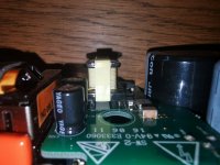
There is a Wickman T1.6A fuse on the board (3rd picture, top left of board). Has that failed open circuit?
Not in Linn devices but I have seen TOP223 being the part that failed. My habit is to replace all electrolytic caps for known good 105 degrees rated industrial ones and the TOP IC. Also check all diodes.
The TopSwitch 223 on the daughter board is only for a 12V "helper" supply, probably for remote and LAN. A max. power of 9.6W cannot be for the speakers. Should be easy to see if it still works, there is even a legend at the 3 pins that go down to the main board, PHV/NHV (rectified mains) and 12VPRI. The latter should read 12V against NHV.
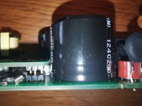
The main power stage is on the lower board with the bigger caps and transformer. Cannot comment much as it is mostly hidden, but it could be a half bridge since a flyback needs no bridge rectifier and filter coil (L203, top right pic), not even for bipolar output.
The main power stage is on the lower board with the bigger caps and transformer. Cannot comment much as it is mostly hidden, but it could be a half bridge since a flyback needs no bridge rectifier and filter coil (L203, top right pic), not even for bipolar output.
Dear all, thank you for your answers. Unfortunately I wasn't able to read you for the last week (due to sickness). Won't be able to have a look at it for the next few days, but I'll do it ASAP. Best regards, Michel
Hi VagrantShadeHello from Switzerland,
........
I also contacted Linn to ask them if hey could provide schematics for the power supply (the product was discontinued 3 years ago), but they refused... they told me to reset the device by pressing a button but it didn't solved the issue.
.........
This post is somewhat old but I see that you refere to something very interesting, namely pressing buttons (inside?) the Sneaky. I cannot make my Sneaky acquire an IP-address and probably need to do some factory reset. From the outside the only option is the "fallback" button but this still require a working network connection.
Inside the Sneaky there are two additional buttons next to the power supply. One i labeles "Fallback" and the other "Main"(?). Are one of these reset-button the one you refere to in your text?
Hi all,
Bit of a hijack of the thread since I have a Sneaky DS with the same symptoms. No longer turning on, no relay click noise when plugging in.
No obvious visually sad components/magic smoke release visible on the boards.
Thanks v4lve lover, jean-paul and Holmer for great hints in this thread.
It seems like the 12V helper supply is dead in my case.
PHV IN - NHV reads 320V DC on my multimeter.
12V PRI - NHV just 0.56V DC, so something is wrong here.
I tried injecting 12V DC between 12V PRI and NHV from a bench supply, it felt dirty but hey, it was already dead. And then it boots and plays music again. Pulling just 40mA from the bench supply. Promising!
So i tried ordering a new TOP223 and replaced that and the two 100uF electrolytic caps. Sadly no improvement, still 0.56V at 12V PRI.
I feel that I'm in a bit over my head and unsure what to try next.
Mailed Linn support with details and pictures and asked nicely to get forwarded to one of the tech people for schematics or component details on the daughter board. But sadly customer support is a "Talk to your nearest Linn reseller"-wall.
Contacted my nearest reseller and they are like, "Yea sure. We can take it and mail it to Linn and they will fix it", for 300€ ... T_T
Any thing else you would recommend i try?
Kind regards,
Robin


Hello,
I ran into the same issues with device not powering except when warming up the powersupply. I then took my smd rework gun and started heating components one by one. When warming up the 22uF capacitor next to the TOP223 (like v4lve lover already mentioned) the power switches on. So I replaced it with a 22uF 100V capacitor I had laying around and now it switches on like normal. Thanks for all the information everybody!
Regards, Jurn
First I heated up the entire PSU with a blowdryer. When I wanted to single out the component that actually malfuncitoned I used the heat blower from my SMD Rework station, so essentialy a more precise blowdryer. ;-)
I am hoping to fix a Finn Sneaky Music DS that is completely dead.
There is mains on what I assume is the bridge rectifier near the mains connector on the PSU
The bridge rectifier measures at least several Meg ohm across any pair of the 4 pins
Presumably this is burnt out?
There is no sign of overheating anywhere nor bulging/leaking capacitors
Any thoughts would be most welcome
Thanks
doug
- Home
- Amplifiers
- Power Supplies
- Debuging a power supply: first steps?