I have two Coleman Filament Regulators (V9). They both worked fine for a while, but one just died for no apparent reason. The raw-DC supply is fine, but the output voltage remains zero. For debugging it would be useful to have a circuit schematic, but I couldn't find one. Would be great if someone could help.
[ Pinging @Rod Coleman ]
[ Pinging @Rod Coleman ]

Here you go! Measurements taken from both the bad and the good board. Without load/tube and with load/tube. Values in V.

I am curious to learn what caused the failure. I have three pairs of these regs running with no issues thus far.
The difference between the input and the output is high - near 6V .
This is more than the guide maximum, though even that level can be managed with a large heatsink and checking of the temperature according to the PDF manual.
But it is good to drop some more voltage in the CRC of the Raw DC to get the input into the specified range 10.1V - 11.2V max. {Loaded)
What does the heatsink look like, or what thermal resistance (⁰C per Watt) and does it have access to free air?
In the meantime a replacement for the power transistor is likely needed - the failure of which would indicate the heatsink temperature is too high.
Check the solder joints around Q5 and output connections are good first though
Hi Rod
Yes, the raw-DC input is high in my measurements. It was closer to the recommended 11 V when both boards/tubes were up and running. Also, I may have set the variac a wee bit high during the test, which would add to the high raw DC. The power transistors are mounted to the base plate of the chassis, and things never got very toasty.
I'll check the transistor then. I guess you're referring to the TF409, correct?
Use a lightweight thermocouple to check the temperature of the heatsink near Q5 (and Q5 itself) is < 50 ⁰C.
Measure a number of times during running to verify the maximum.
The thermocouple that is included with some types of low cost DMMs is good.
The interface between Q5 and the heatsink must be perfectly flat, carefully cleaned, and very lightly, evenly greased with a quality thermal grease.
I'm taking the liberty of emphasizing the transistor temperature, since it's by far the most likely cause of any failure, unless the output is inadvertently shorted.
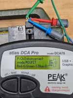
I removed the TF409 from the board and it tests fine in the transistor tester (see attached photo). Can you provide the circuit schematic so I am not fishing in the dark? I am hoping to not have to reverse engineer the PCB traces...
Thanks
Matthias
Thanks
Matthias
Attachments
Unless the tester operates at Ampere level, it may still be suspect.
The only other possibilities are solder joints: input and output connectors, or R1, or R9. The Q5 drive voltage (R7) was present and correct in your measurements, so no other components are involved.
I'm happy to support voltage probe debugging, by email - with great patience, but I don't issue schematics.
Problem solved. After staring and poking at the board I found a tiny crack in one of the PCB traces near the power transistor. Once I found it the fix was easy.
- Home
- Amplifiers
- Tubes / Valves
- Debugging Coleman Filament V9 regulator