Happy new 2023! Well, not that happy for me as I'm having tough times debugging a channel of my primary amplifier. It has served me well for about 8 years.
It's a TSSA v1.8 CFA amp from SITO audio here on DIYA. Unfortunatelly, Sonny, amplifier's designer is not hanging around anymore.
I hope to get some debugging help from more expert members than me.
The trouble started after testing different PSUs and grounding techniques. Long story short I have one amp channel working and the other not, acts weird.
All worked with stable bias with the bulb tester and without the bulb tester. Just after plugging it to my main system it went south.
It could have been due new thermal compound on mosfets and insulators. Even though I have tested all for non-conductivity before firing up.
Can't come up for any other causes for malfunction at the moment.
The driver mosfets seem to be alive. Measuring with DMM show up same values between not functioning and functioning channel.
I have put two amplifier modules side by side and went through most of the R and Q components measuring them in circuit, comparing between the channels.
Couldn't find any discrepancies except Q8:
positive on the gate, negative on the source
1.856V good channel
1.129V bad channel
positive on gate, negative drain
1.8V good channel
1.055 V bad channel
Not sure if that helps anything.
The amp is powered with double mono PSU. At the moment I have only one channel mounted and connected for testing.
Connex SMPS 300RE PSU rail voltages when unconnected are +35V 0 -35V
When connected though it reads weird. Please have a look at this video showing reading between positive and 0
Also please take a look at this video showing jumpy offset readings.
The amplifier module also makes a pulsating "tsk, tsk, tsk..." sound.
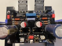
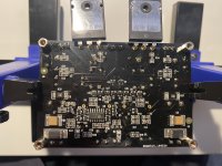
Attaching pics of both sides of the malfunctioning amp module.
Any help appreciated 🙏
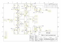
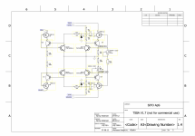
Edit: Schematic attached with author's permission.
It's a TSSA v1.8 CFA amp from SITO audio here on DIYA. Unfortunatelly, Sonny, amplifier's designer is not hanging around anymore.
I hope to get some debugging help from more expert members than me.
The trouble started after testing different PSUs and grounding techniques. Long story short I have one amp channel working and the other not, acts weird.
All worked with stable bias with the bulb tester and without the bulb tester. Just after plugging it to my main system it went south.
It could have been due new thermal compound on mosfets and insulators. Even though I have tested all for non-conductivity before firing up.
Can't come up for any other causes for malfunction at the moment.
The driver mosfets seem to be alive. Measuring with DMM show up same values between not functioning and functioning channel.
I have put two amplifier modules side by side and went through most of the R and Q components measuring them in circuit, comparing between the channels.
Couldn't find any discrepancies except Q8:
positive on the gate, negative on the source
1.856V good channel
1.129V bad channel
positive on gate, negative drain
1.8V good channel
1.055 V bad channel
Not sure if that helps anything.
The amp is powered with double mono PSU. At the moment I have only one channel mounted and connected for testing.
Connex SMPS 300RE PSU rail voltages when unconnected are +35V 0 -35V
When connected though it reads weird. Please have a look at this video showing reading between positive and 0
Also please take a look at this video showing jumpy offset readings.
The amplifier module also makes a pulsating "tsk, tsk, tsk..." sound.
Attaching pics of both sides of the malfunctioning amp module.
Any help appreciated 🙏
Edit: Schematic attached with author's permission.
Attachments
Last edited:
Yes, forgot to add! I've got a schematic, but hesitant to post it, as it is not in a public domain. I think I have no choice but to reveal it in private.
Last week I had one channel on mine stopped working when I was listening to music.
After much debugging I found that R1 was burned. Now everything is back to normal after replacing the resistor.
Before that I checked all the semis according to the schematic and I advise you to do so. BJTs with the diode function and the mosfets with the resistance function on your multimeter. Print the schematic and mark the good ones until you find the culprit. I would start with U9 but check all of them. Check the resistors too.
Thank you George. I'm about to do as per your suggestion – a more through second round of inspections. And it turns out I don't have much info on U9 or any U for that matter from the schematics. It has no part number marked like other actives. All I can understand is that it's a dual transistor package and I can see on the board with written R8 49 t on the package.

Pinout most probably like this one: https://gr.mouser.com/ProductDetail...cbukviAXguXbSiWnRz-FywSRVMnm6hxxoChZIQAvD_BwE
I have attached the schematic with the permission from the author.
Went through all active parts and resistors. They all seem in okey and give readings conform to those of the working channel and schematic. Hard to believe it. There's still a chance I have overlooked overlooked something. In that case, I'm much more confident about resistors and bjts being correct than mosfets. Measuring them in circuit as I understand, I can only measure them in one state? Haven't checked any caps.
Went through all active parts and resistors. They all seem in okey and give readings conform to those of the working channel and schematic. Hard to believe it. There's still a chance I have overlooked overlooked something. In that case, I'm much more confident about resistors and bjts being correct than mosfets. Measuring them in circuit as I understand, I can only measure them in one state? Haven't checked any caps.
I couldn't find it at first either, but it's embedded in original post. I didn't know that was possible...
If I interpret correctly from the first video, you're seeing only a few volts from the power supply; seems it's probably in current limit state, so interaction between amp and supply throws everything into question, I believe.
Given supply seems to work with other channel, problem probably lies in the amp. Do you have a bench supply with adjustable voltage and current limiting?
Given supply seems to work with other channel, problem probably lies in the amp. Do you have a bench supply with adjustable voltage and current limiting?
correctyou're seeing only a few volts from the power supply
If I interpret correctly from the first video, you're seeing only a few volts from the power supply; seems it's probably in current limit state, so interaction between amp and supply throws everything into question, I believe.
Given supply seems to work with other channel, problem probably lies in the amp. Do you have a bench supply with adjustable voltage and current limiting?
I wish I had, all this could have been so much easier
By power up, The amp accelerate the bias current for 1 second to or so to 1 - 1.5A. And then it settles. There is two current mirrors.
Prior to the mostet there is a buffer/driver transistor. Ksa1381estu and ksc3503estu.
If they break, then I have them in stock. I have not seen them break in this amp yet.
- One who sets a basic current.
- One who sets bias current in the lateral mosfets and the current offset.
Prior to the mostet there is a buffer/driver transistor. Ksa1381estu and ksc3503estu.
If they break, then I have them in stock. I have not seen them break in this amp yet.
Buffer driver transistors on my board are 2SA1381 and 2SC3503.
Voltage drop In diode mode:
2SA1381
Base to Emiter 0.702V
Base to Collector 6.901V
.OL when reversed
2SA1381
Emiter to Base 0.717V
Collector to Base 7.132V
.OL when reversed
I think they are alright?
Attaching the pic of my one channel setup.
Voltage drop In diode mode:
2SA1381
Base to Emiter 0.702V
Base to Collector 6.901V
.OL when reversed
2SA1381
Emiter to Base 0.717V
Collector to Base 7.132V
.OL when reversed
I think they are alright?
Attaching the pic of my one channel setup.
Attachments

What's the best way to measure laterals in circuit?
ECW20P20
Gate to source resistance 316R
Gate to drain 1k84 when in simple resistance mode
But when in continuity the same position gives 202R if in ohms mode.
ECW20P20
Gate to source resistance 316R
Gate to drain 1k84 when in simple resistance mode
But when in continuity the same position gives 202R if in ohms mode.
If you had a friend with an oscilloscope and a dac.
This app with can generate a pure tone for testing. https://www.szynalski.com/tone-generator/
This app with can generate a pure tone for testing. https://www.szynalski.com/tone-generator/
- Home
- Amplifiers
- Solid State
- debugging a TSSA 1.8