Interesting that there is more screen current and less plate current on both channels than schematic suggests. However this looks more correct from the datasheet. I suppose it could be oscillation at VHF which you won't see on the pico but usually the plate voltages will change as you move you hands nearby. You could check the first stage only with no NF by removing valves from the output. Its a very weird problem you have. Maybe check U2 too.
Last edited:
Slightly OT perhaps:
I have a small tube amp I made recently, my first amp to be totally clear.
My amplifier shows a similar ringing of 2 or 3 cycles in response to square wave signal at max power output (say less than 1% THD)
I have not been able to eliminate it, other than by using a capacitor in parallel to the feedback resistance in the output stage (no GNFB, only LNFB plate to grid).
Using a capacitor large enough to round the transition merely limited the entire BW, to perhaps 17kHz. Without this the BW extends to 40kHz without displaying a peak or notch above 40kHz. I believe it is perhaps due to OPT and the way I have used it, 8R load on 4R tapping.
Whether this helps or not, is anyones guess.
It's a damped ringing, so is this an indicator of something sinister? Or merely a slightly undamped FB resonance?
You can adjust R37 and R39 to get the correct current through the driver bottles. DMOS vary all over the place when it comes to calculating Rset.
Doh! Of course... yes, I'll do that and see if there is any ringing the grids of the output valves. Will also start using my Rigol scope and an external sig gen.Interesting that there is more screen current and less plate current on both channels than schematic suggests. However this looks more correct from the datasheet. I suppose it could be oscillation at VHF which you won't see on the pico but usually the plate voltages will change as you move you hands nearby. You could check the first stage only with no NF by removing valves from the output.
Hmm, yes it could be U2 oscillating... From a quick google: "depletion mode mosfets also have a tendency to oscillate". But I'd hope the stopper would stop that. Maybe it's a dud.Its a very weird problem you have. Maybe check U2 too.
To recap:
- Disconnecting the GNFB makes no difference
- Altering the local NFB shunt capacitors makes no difference
- Disconnecting the local NFB by removing the output tubes will then determine if the ringing is in the driver stage or output stage (including OT)
- If it's the driver stage it could be the CCS
Ah yes, that could be another change to make. Tacking in 2.2k across the 200r to lower it a bit. Although I'm getting OK THD readings - 0.153% and 0.157% for L & R.You can adjust R37 and R39 to get the correct current through the driver bottles. DMOS vary all over the place when it comes to calculating Rset.
mondogenerator,
A schematic of your "ringing" amp might be helpful.
Details of output transformer manufacturer, primary impedance, output tube(s), feedback, etc.
Also, a screen shot (a 10kHz squarewave, and the time from each peak of the ring to the next peak of the ring.
Otherwise, much troubleshooting is in the dark.
A new thread might be helpful.
Last edited:
I wasnt thread jacking...it was late (for me) and I didn't get my point across.
Is this ringing apparent only at Full Power? reading back I see, that it is noted at 1W (which isnt full power me thinks)
FWIW ringing only occurs for my circuit, at close to max output, and at 1kHz square wave input - at 10k little to no ringing at all. BW intentionally limited to 35kHz of thereabouts. Also my amp.is a SET. So the only similarity is a slight ring.
Not entirely sure that this ringing is a problem at all!
I'll get me coat
Last edited:
If you still have a notch with all the NFB disconnected then the only thing with enough Q factor is the output transformer. Could be a shorted turn (but that's usually much more obvious).
mondogenerator,
You said the ringing shows up on a 1kHz square wave, not so much on a 10kHz square wave.
With a 1 kHz square wave, what is the time of a cycle of ringing (from peak to peak)?.
Are you seeing the ringing with a resistor loading the amp?
Or are you seeing the ringing with a loudspeaker loading the amp?
Is your amp different than the amp that is discussed in this thread?
If so, the causes of ringing can be completely different.
It's there at 1W output which is miles away from full 18W output.Is this ringing apparent only at Full Power? reading back I see, that it is noted at 1W (which isnt full power me thinks)
Thanks - will hopfully get a chance tomorrow to get it on the table for testing.If you still have a notch with all the NFB disconnected then the only thing with enough Q factor is the output transformer. Could be a shorted turn (but that's usually much more obvious).
If the OPT has poor coupling between the two halves of the primary at 40kHz then it is possible that the two feedback paths send quite different signals back. These could create a peak or a dip in response.
Silly comment - on your photo your unused output transformer wires (orange and green) are not insulated. They are not touching the output post.
Yeah - I hope (in a strange way) it's something like this. I really hate desoldering from PCBs as it tends to go wrong and pads lift etc.If the OPT has poor coupling between the two halves of the primary at 40kHz then it is possible that the two feedback paths send quite different signals back. These could create a peak or a dip in response.
If I remove the output valves I can scope their grids (by R4 and R5) and check what the square wave looks like there for each side.
However, I'm guessing this would still include the OT via the local feedback as shown in the attached. If so I can also check the output but the level might be very low.
I can try a few things with the CCS too - some posts indicate if the stopper is too large a VHF oscillation can occur. So I can make it smaller and see what happens.
As the amp is currently they are clipped flush and insulated with electrical tape. No chance of contact with the output post. However, could their proximity to each other influence things? Worth checking.Silly comment - on your photo your unused output transformer wires (orange and green) are not insulated. They are not touching the output post.
Attachments
Hot iron with joint fully melted will stop you lifting tracks. I would start by swapping over the transformer primaries (with transformer NF disconnected) and see if the issue stays with the transformer.
I don't think you have VHF oscillation usually volts change when you put hands/scope near.
I don't think you have VHF oscillation usually volts change when you put hands/scope near.
Last edited:
I think it is the OT...Hot iron with joint fully melted will stop you lifting tracks. I would start by swapping over the transformer primaries (with transformer NF disconnected) and see if the issue stays with the transformer.
I don't think you have VHF oscillation usually volts change when you put hands/scope near.
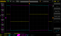
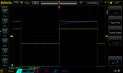
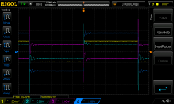
I hooked up my analogue sig gen to the input, removed the two output valves on the right channel, and scoped the grid resistors with my Rigol.
Attached is the trace with input, and the two grids at 1kHz and ~1Vpp input. Also attached is same conditions but one grid inverted and lowered / zoomed.
Then the same input with the output valves replaced, signal across the load in dark blue.
To me, that means it has to be OT, no?
Only way to confirm is to do as you suggest.
Attachments
This post suggests something similar with an Edcor OT: Faulty output transformer? | Page 2 | Audiokarma Home Audio Stereo Discussion Forums
1. Why are those 820pF caps connected from each primary tap to ground?
The primary center tap is at AC ground.
Effectively, 820pF is connected from the center tap to the Push winding;
and 820pF is connected from the center tap to the Pull winding.
820 pF is 9,705 Ohms at 20 kHz.
The 820pF and 1/2 of the primary is a resonant circuit.
the other 820pF and the other 1/2 of the primary is a resonant circuit.
If you are going to use a cap across the primary windings, then at least use a resistor in series with each 820 pF cap.
2. Resonances ring.
3. re: post # 34, That ring frequency is about 8 or 10 kHz.
4. I think 820pF caps may be part of the problem.
You are driving the primary from high impedance plates of pentodes.
The only resonance damping is from:
A. The negative feedback
and . . .
B. The load resistor across the secondary. And the load resistor can not make up for the Leakage Inductance of the Primary/Secondary.
5. I am not convinced that the output transformer is the problem.
But even if it is, you may find that some adjustment of the 820pF plus a series resistor for each leg (push and pull) may optimize the amp.
Last edited:
For my post # 36, Here is an added thought:
Item # 4. A. The negative feedback
The phase and amplitude versus frequency of the feedback signal is affected by the
Leakage Reactance of the Primary/Secondary.
Item # 4. A. The negative feedback
The phase and amplitude versus frequency of the feedback signal is affected by the
Leakage Reactance of the Primary/Secondary.
OK - been busy today. Had it on the kitchen table, disassembled. Findings:
I'm tired, it's been a long day. Been thinking what the issue could be. Point 3 above seems to be key. Why would adding GNF increase ringing? Could the primaries be swapped? Is it something in the driver stage, ie where the FB is applied?
I've also realised I might have added the 820p caps back in ahead of returning the 220k feedback resistors - not sure if that means the 820p could still be an issue with the 2nd image below. Might re-do all the readings again in a more systematic manner.
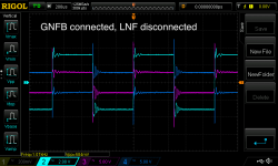
- With no feedback connected, there is no ringing
- With only LNFB connected there is no ringing
- When applying GNFB the ringing appears
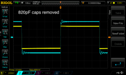
- Removing the 820p caps to ground in the LNFB loop makes no difference
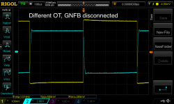
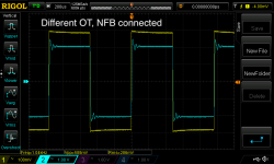
- Using an entirely different OT shows the same behaviour (once I swapped the primaries)
1 above showed no ringing, and seemingly no notch as I went up in frequency.If you still have a notch with all the NFB disconnected then the only thing with enough Q factor is the output transformer. Could be a shorted turn (but that's usually much more obvious).
5 suggests it's not the OT.I would start by swapping over the transformer primaries (with transformer NF disconnected) and see if the issue stays with the transformer.
So 4 and 5 I think address your suggestions.4. I think 820pF caps may be part of the problem.
You are driving the primary from high impedance plates of pentodes.
The only resonance damping is from:
A. The negative feedback
and . . .
B. The load resistor across the secondary. And the load resistor can not make up for the Leakage Inductance of the Primary/Secondary.
5. I am not convinced that the output transformer is the problem.
But even if it is, you may find that some adjustment of the 820pF plus a series resistor for each leg (push and pull) may optimize the amp.
I'm tired, it's been a long day. Been thinking what the issue could be. Point 3 above seems to be key. Why would adding GNF increase ringing? Could the primaries be swapped? Is it something in the driver stage, ie where the FB is applied?
I've also realised I might have added the 820p caps back in ahead of returning the 220k feedback resistors - not sure if that means the 820p could still be an issue with the 2nd image below. Might re-do all the readings again in a more systematic manner.
Attachments

Last edited:
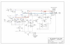
smoking-amp sent me this schematic yesterday, its slightly different from yours.
Notice there are some differences in the NFB in that a zero has been added (C1).
I think would expect your amp to ring as there's no lead-lag compensation.
http://www.pmillett.com/file_downloads/dcpp_mb_sch.pdf
Notice there are some differences in the NFB in that a zero has been added (C1).
I think would expect your amp to ring as there's no lead-lag compensation.
http://www.pmillett.com/file_downloads/dcpp_mb_sch.pdf
Yes, very good point. Easy one to try and probably should have done so first! Will report back.smoking-amp sent me this schematic yesterday, its slightly different from yours.
Notice there are some differences in the NFB in that a zero has been added (C1).
I think would expect your amp to ring as there's no lead-lag compensation.
http://www.pmillett.com/file_downloads/dcpp_mb_sch.pdf
Might help to work through this:
Amplifier Compensation.
Last edited:
- Home
- Amplifiers
- Tubes / Valves
- DCPP - 'notch' in frequency response