Hi Craig,
That could be. Just being on will not make a board conductive. Now, if they used that special glue - yes. That is a distinct possibility as the glue requires heat and time to become active.
-Chris
That could be. Just being on will not make a board conductive. Now, if they used that special glue - yes. That is a distinct possibility as the glue requires heat and time to become active.
-Chris
Max, Anatech,
Thanks. I'll keep ya posted and see how it goes. It should be here shortly.
And we all know how that goes.
Cheers,
Thanks. I'll keep ya posted and see how it goes. It should be here shortly.
And we all know how that goes.
Cheers,
Hi Chris,
I'm going to be replacing the caps on this and I wondering how to look at the "pip" on the mains power supply to determine if the big caps are still good?
Yes, I know I can do ESR and Capacitance test along with D, Q, and theta I think (egg with a center line)? These would be looked at with the DER DE5000.
However checking with the scope to get a visual of the relative heath with the scope would be helpful to know.
Cheers,
Hi Sync,
Sure thing.
Look at the ripple on your positive main supply. If you go to AC coupling, you can "zoom in" on the ripple component. With new capacitors, you should see a rising trace that reverses direction and heads down again. With a really good new capacitor, the peak will be nicely curved. As a capacitor becomes larger, or less good (either one), you will see that the leading edge of the trace will become more pointed. With a capacitor that has past it's "best before date", you will notice that the peak will have stretched vertically and will drop vertically before hitting the rear slope and flattening out again. A really bad capacitor will have a larger AC ripple component that drops quickly until hitting the leading edge trace again. You may by this point measure well over 10 volts peak for that leading edge.
Looking at the negative rail will show you something similar except all the polarities are reversed.
Playing music or a tone into a dummy load will also show up on the supply rails as well. Using a test tone into a specific load resistance (amplifier output) can also give you great information as to the health of the capacitors.
This stuff needs you to become familiar with it in order for the results can be considered to be a time saver.
-Chris
Playing music or a tone into a dummy load will also show up on the supply rails as well. Using a test tone into a specific load resistance (amplifier output) can also give you great information as to the health of the capacitors.
I think you are saying I can inject a tone (or music) on the input to the amp.
The amp affixed with an 8 ohm 75W dummy load on the amp's output.
Set my scope with 10x probe and probe and view:
1. The output signal
2. The positive supply rail
3. The negative supply rail
4. Specific capacitors in the amp
Cheers,
Hi Sync,
More like looking at the ripple on the supply rails in some detail. Adding music or tones can be done as a matter of interest. Looking at a tone on the supply rail at a specific power level into dummy loads might give you a more controlled picture.
-Chris
More like looking at the ripple on the supply rails in some detail. Adding music or tones can be done as a matter of interest. Looking at a tone on the supply rail at a specific power level into dummy loads might give you a more controlled picture.
-Chris
Hi anatech,
That is what I was thinking too. Tones will give me a more stable scope image then music when looking at the supply rails. I can use a few different test tones and see what they look like.
But that is down the road a bit. First I'll need to do some cleaning.
Aside from that, I've got the time to work on things but no bench as I'm still trying to install shelves for gear and supplies. It's a nightmare.
In time though it will be useable as opposed to the Jim Williams look, which is fine if you have space to move stuff around--now that I'm a dad and have a better half, things can't be moved like they used to be.
Imagine that?
I always appreciate your insights.
Cheers,
Hi Sync,
When looking at supply ripple, just change the trigger on your 'scope to "line".
-Chris
When looking at supply ripple, just change the trigger on your 'scope to "line".
-Chris
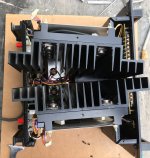
Well ya'll the amp arrived today and was packed well. Taking it out was difficult, it is heavy.
It looks very nice, not rode hard and put up wet.
Then I opened it up and check out the all the parts. It was rode hard and the boards are covered in what ever it is thats there. Then it seeped into the heat sinks.
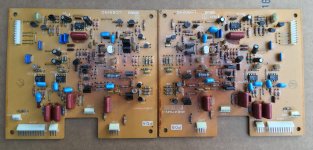
These are the pre amp and driver boards connected to the heat sinks.
The center board(s) I'll have to go look at it is even nastier. It looks like it had the panasonic ECQ capacitors but with the triangle logo (Matsushita or Mitsubishi). Those things are dark, dark, dark, and covered in what looks like sludge.
I can't recall ifs on that board in center, there is a cap board with what looks like the small panasonic snap in caps TS? But along with the sludge there is like black soot that is in there. I'm not sure which parts are good and which aren't.
We'll see how the boards sort out. I've got the left side out and that part of the channel disconnected. Some transistors out.
I could have swarn someone used arctic epoxy to affix them.
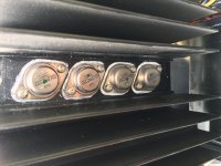
Two outputs came out easy, as the TO-3 screws were loose which kind of confirms that someone was in there and closed it back up, didn't want to fool with it.
Now I can see why.
I'm not even going to try and apply power to this until it is at least all cleaned up. With all that crap along everything and it melts down the board when it gets toasted.
The bottoms of all the boards have that layer of run goop on them. Woo Hoo, it's gonna be fun.
Film at 11.
Cheers,
It looks very nice, not rode hard and put up wet.
Then I opened it up and check out the all the parts. It was rode hard and the boards are covered in what ever it is thats there. Then it seeped into the heat sinks.
These are the pre amp and driver boards connected to the heat sinks.
The center board(s) I'll have to go look at it is even nastier. It looks like it had the panasonic ECQ capacitors but with the triangle logo (Matsushita or Mitsubishi). Those things are dark, dark, dark, and covered in what looks like sludge.
I can't recall ifs on that board in center, there is a cap board with what looks like the small panasonic snap in caps TS? But along with the sludge there is like black soot that is in there. I'm not sure which parts are good and which aren't.
We'll see how the boards sort out. I've got the left side out and that part of the channel disconnected. Some transistors out.
I could have swarn someone used arctic epoxy to affix them.
Two outputs came out easy, as the TO-3 screws were loose which kind of confirms that someone was in there and closed it back up, didn't want to fool with it.
Now I can see why.
I'm not even going to try and apply power to this until it is at least all cleaned up. With all that crap along everything and it melts down the board when it gets toasted.
The bottoms of all the boards have that layer of run goop on them. Woo Hoo, it's gonna be fun.
Film at 11.
Cheers,
Last edited:
Hi Sync,
I guess you may as well start by stripping it and cleaning it up. You can test some of the parts easier while they are out. Check all the outputs before greasing them up for insertion. See if you can match them while they are out. You can also go over all the solder connections that go to heavy components, and to any transistor sockets. Have a good look at the rest of the solder connections before putting it all back together. Of course, make sure the board doesn't have conductive stuff on it.
Best, Chris
Parts
Here's some of the parts from the amp.
The boards look better then they are. It was over cast and the sun was going down. The board are covered in a this oozing sticky kinda something. It doesn't show up looking straight on. But, if the light hits it a certain way, that surface will look like the shimmer of the ocean or lake. That my friends is the dreaded oxen scheisse vee don't vont.
If you zoom in you can see some of it.
In the first pic zoom in in the lower left corner and look at the Film cap and look at the resistor adjacent to and below the three transistors. It got so hot it looks to have boiled through the cement layer.
Look at the resistor adjacent and just above. Little MEs suffering from heat stress. If there is any good to come out of this is note how the heat stress is UNIFORM along the resistor body--Yes.
Uniform thermal baking is preferred! Less distortion.
Warm at one end and hot at the other, is what we don't want. That leads to much higher distortion.
The plastic connectors just flake apart from being baked. Though I only lost one corner. I also broke two of the plastic snap on clamps that hold the outer board on to the heat sink. One corner connector just vaporized.
Enjoy,
Attachments


Last edited:
Hi Sync,
Looks good aside from the coating you mentioned. So that's good news anyway.
Have you been able to measure any conductivity? The coating might be some kind of conformal coating. I'm thinking this because you mentioned that the board seems to be evenly covered. Of course, we don't want a conformal coating on these PCBs. To remove that, you need to use a solvent for that purpose. If you have to soak the PCB, you'll have to replace the capacitors and pots (remove them 1st) if they remained on the board.
I was just guessing as to what that coating could be. Capacitors don't generally leak that much and certainly wouldn't coat a PCB evenly.
-Chris
Lost what I was writing again.
Look in the two board pic, the right board, labeled PDB you can see the contamination better. I think it's a combination of glue, electrolyte, and flux from wave soldering. Then what ever was left got mixed and migrated. The board are shown upside down. Look at some of the edges of the board and components.
It won't bring the amp out of protection with the goop. It is kind of sticky honey-esque.
The back side of the board were much worse, maybe it was left over flux remover? It's definitely not a conformal coating as I have a couple of other boards that have it and it doesn't look anything like these boards. Conformal coatings I've seen have a thick clear hard coating on both sides of the board.
Now, that doesn't mean there are lesser conformal coatings.
If I ever get the bench and sheves together again I could problaby find the boards and when I do, I'll include a pic.
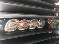
Update, all 16 output transistors test good, all 6 driver transistors test good too.
One side has matched Vbe devises and are close gain grouping. This with a Peak Atlas DCA55 Transistor tester.
Okay back to work for me.
I'd build a higher voltage transistor tester for my TO-3 Devices but I can't find schematic or layout for it. I don't have access to a curve tracer either. Bummer that is.
Cheers,
Look in the two board pic, the right board, labeled PDB you can see the contamination better. I think it's a combination of glue, electrolyte, and flux from wave soldering. Then what ever was left got mixed and migrated. The board are shown upside down. Look at some of the edges of the board and components.
It won't bring the amp out of protection with the goop. It is kind of sticky honey-esque.
The back side of the board were much worse, maybe it was left over flux remover? It's definitely not a conformal coating as I have a couple of other boards that have it and it doesn't look anything like these boards. Conformal coatings I've seen have a thick clear hard coating on both sides of the board.
Now, that doesn't mean there are lesser conformal coatings.
If I ever get the bench and sheves together again I could problaby find the boards and when I do, I'll include a pic.
Update, all 16 output transistors test good, all 6 driver transistors test good too.
One side has matched Vbe devises and are close gain grouping. This with a Peak Atlas DCA55 Transistor tester.
Okay back to work for me.
I'd build a higher voltage transistor tester for my TO-3 Devices but I can't find schematic or layout for it. I don't have access to a curve tracer either. Bummer that is.
Cheers,
That's just flux - unless it isn't dry and hard. It could be something on top of the normal appearance of flux.
-Chris
-Chris
Started removing parts. Ugly mess and time consuming. Look at the second pic in post#33. Then look at the bottom center of each board, the cap, diode jumper. Corroded through each board.
Then look at the first and last pics of post #33. IN the middle of the middle of the board, where the dark brown glue is all those parts are corroded. through the board.
It's hard getting the stuff off, and the silk screen goes with it, sadley. It doesn't want to melt off. But with ISO it starts to dissolve...and these are thick layers of crud, it take long time.
And the beat goes on....
Cheers,
- Status
- Not open for further replies.
- Home
- Amplifiers
- Solid State
- DC Servo Problems Yamaha P2202M