Hi,
The phono stage with it's DC coupling (or thereabouts) is draining your PS which accounts for the dulled flattenend sound.
I said so before, DC phono stage is just plain stupid. Records aren't mirror flat, cartridge/tonearm combos transmit their resonance as an electrical signal to your preamp and so on. These drain your preamp's PS to the point that there's just not enough left to render the true signal correctly.
IOW, your signal is swamped in PS modulation.
You like whatever you like but a good circuit should not have any sound of its own. Microphones, vinyl, tonerams and cartridges often add already so much colouration to the sound already....Why add yet an other?
Should you not be aware of a microphone's own signature I'd highly recommend Dave Wilson's Records. One of them has each side recorded with a different mike. If you can't tell the difference, don't bother with neutrality. It may bother you later when your hearing becomes more discriminate.
In audio everything makes a difference, whether it matters to you is an entirely different issue. Many changes you make to your system are just that, audible as they may be they may well take you further from the truth.
It's therefore important one sticks to a wellknown reference to which things can be compared. Anything else may well be change for change's sake....
Cheers, 😉
The line preamp sounds very good, with an authoritative full bodied, sweet character. The phono is however problematic. It has low output and the sound is very dull (closed in – almost like a pocket radio!).
The phono stage with it's DC coupling (or thereabouts) is draining your PS which accounts for the dulled flattenend sound.
I said so before, DC phono stage is just plain stupid. Records aren't mirror flat, cartridge/tonearm combos transmit their resonance as an electrical signal to your preamp and so on. These drain your preamp's PS to the point that there's just not enough left to render the true signal correctly.
IOW, your signal is swamped in PS modulation.
You like whatever you like but a good circuit should not have any sound of its own. Microphones, vinyl, tonerams and cartridges often add already so much colouration to the sound already....Why add yet an other?
Should you not be aware of a microphone's own signature I'd highly recommend Dave Wilson's Records. One of them has each side recorded with a different mike. If you can't tell the difference, don't bother with neutrality. It may bother you later when your hearing becomes more discriminate.
In audio everything makes a difference, whether it matters to you is an entirely different issue. Many changes you make to your system are just that, audible as they may be they may well take you further from the truth.
It's therefore important one sticks to a wellknown reference to which things can be compared. Anything else may well be change for change's sake....
Cheers, 😉
Re: regulated PSU for phono stages
Hi,
AFAIK the circuit has separate AC windings for the differential valve which are left floating. This hasn't been a problem for 30 years of service.
If you should ever build the circuit and would encounter problems please PM me. I'm sure you won't have to though.....
Cheers, 😎
Maitchy said:
Hmmm, I also think there is a dangerous potential (pun) problem with the ECL85 regulator cathode-to-filament voltage UNLESS it has its own 6.3v winding and that winding is tied to some potential around about half the output voltage. I really think solid state voltage regulators have far less problems to watch out for, and (if correctly designed) can introduce no sonic differences... and having separate regulated outputs for each stage of each channel is way less impractical than their valve/tube counterparts.
P.S. DC heater supplies for sensitive input stages is a pretty good idea, and that is one supply where solid state regulators are essential.
Hi,
AFAIK the circuit has separate AC windings for the differential valve which are left floating. This hasn't been a problem for 30 years of service.
If you should ever build the circuit and would encounter problems please PM me. I'm sure you won't have to though.....
Cheers, 😎
fdegrove said:
The phono stage with it's DC coupling (or thereabouts)
Greetings Frank. Please decipher the above.
analog_sa said:
Greetings Frank. Please decipher the above.
Hi P.,
I'm afraid I didn't express myself very well.
It's not direct coupling (as in without DC blocking cap) that's going to drain the PS but the mere fact that extreme LF garbage caused by record warps and tonearm/cartridge resonances is passed from stage to stage and sees itself amplified as it passes through these various stages when you do not limit the preamp's frequency response early on.
Cheers, 😉
Hi fdegrove, thanks for your interest and input.
The phono stage with it's DC coupling (or thereabouts) is draining your PS which accounts for the dulled flattenend sound.
I'm not technical enough to discuss your statement but it 'rings' true because I can hear some 'ticks' every now and then which I suspect are coming from the power supply.
From your reply I can't conclude which is at fault, whether the phono stage or the PS. Your statement that "DC phono stage is just plain stupid" sounds rather strange considering the members who enjoyed the circuit and the sound. They said so in this and related threads.
At a practical level, can you please suggest any remedies so I can at least 'savour' the fruits of my efforts !!! My PS is driven by a 250-0-250 trafo into an EZ90, feeding a 4-section RC network. Do you think that replacing the valve rectifier with SS will improve the drive capability enough to handle the combined phono and linestage circuits?
Thanks a lot for your help.
Joe A.
Hi,
@Sonata149
What you could do is measure the frequency response of your preamp for starters.
If the LF repsonse extends well below say 15Hz chances are you'll also be amplifying LF garbage caused by tonearm/cartridge resonances and record warps.
Whilst playing a record you could also hook up a VM to the B+ of the phono stage and monitor the voltage.
Ideally it should remain pretty constant if you notice serious sags your preamp obviously can't cope with the demands of the signal.
This should be audible as a lack of dynamic range especially during bass heavy signals. You may also notice the woofer unit moving in and out (pumping) without any obvious music related cause.
Changing the power supply may help but it's hard to give good advice without tracking down the problem first.
Keep in mind that I'm not criticizing the circuit as such, just pointing out some stuff to watch out for.
Hope this helps, 😉
Hi all, especially those who helped me trace the problem with this amplifier.
I changed the 10Meg (groundleak?) resistor (paralleled it with a 4M7 really) and modified my PS (250v solid-rectified followed by a 4 section RC network). Filament is a 6.3ac bridge rectified followed by a 10,000uF cap. My project involved both this phono and linestage proposed elsewhere by Kwei YW.
The amplifier is working OK now, with a very good sound as described by other posters in this thread. My problem is about an audible hum on the phono stage which increases with increased volume. I'm not sure if this is inherent in the circuit (valves being noisier) or if it is a problem with my wiring.
I followed Kwei's earthing (grounding?) instructions and especially Kofi Anan's diagram in http://www.diyaudio.com/forums/showthread.php?s=&threadid=54534&perpage=25&pagenumber=5 .
I might as well say I have a Rega RB300 arm (with a Nagaoka MP20) which has no ground wire that connects to phono earth.
Have any members who built this preamp had a similar problem?Maybe they can lead me to eliminate this hum, which though not excessive and unobtrusive during record play, is still notable between records.
Thanks and regards to all, especially Kwei (TL) for a really good sounding integrated preamp.
JA
Hummmm?
Hmmm. Hummm? Several possibilities, so it is good to narrow down where it is coming from, e.g. is it still there if you replace the audio input with a plug that has a small resistor with very short leads, wired from signal to ground?
But do check the dc voltage on the heater... you may need a series resistor before that 10mF cap, or a voltage regulator (or both, since you will be getting massive current spikes at the top of each cycle which may radiate back into the input circuit... people forget to include a series resistor in solid-state power supplies, and wonder why the hum gets worse when they increase the power supply capacitor!). Can you look at the hum on a 'scope and see whether it is pure fundamental, or rectified mains, or spikey?? I'm also curious to know the plate voltage now that the grid resistance has been reduced.
Mark
[...] limit the preamp's frequency response early on.
Is there a simple way to do this, e.g. insert an RC highpass before ECC83's grid or reduce the coupling C between both stages?
I've just finished the power supply for this amp (Tube rectified LCRC*6 with rather modest total capacity ~ 160µF) and PS sag wasn't a criterium I took into consideration when designing.
Simon
fdegrove said:
It's not direct coupling (as in without DC blocking cap) that's going to drain the PS but the mere fact that extreme LF garbage caused by record warps and tonearm/cartridge resonances is passed from stage to stage and sees itself amplified as it passes through these various stages when you do not limit the preamp's frequency response early on.
One cannot stress this enough. Apart from the explanation given by Frank, there is also the fact that everything at such a low frequency level is amplified by about 10 in the RIAA compensator.
I am fond of using NFB to do my RIAA thing. With no extra components, by just proportioming the existing stuff right at below say 35 Hz, one can already effect a useful low-cut characteristic of some 9 dB/octave.
Klimon said:
Is there a simple way to do this, e.g. insert an RC highpass before ECC83's grid or reduce the coupling C between both stages?
I've just finished the power supply for this amp (Tube rectified LCRC*6 with rather modest total capacity ~ 160µF) and PS sag wasn't a criterium I took into consideration when designing.
Simon
Hi,
Best place to do this is before the RIAA correction takes place.
Or let your RIAA network take care of it for you but that may well upset the first amplifying's stage(s) PS.
All in all much ado about nothing really, except for the misleading "DC" amplifier title of the thread there's no particular reason the preamp shouldn't work as described neither is there anything to be particularly concerned about other than the one and only truly important ingredient, the PSU.
Cheers, 😉
P.S. Greetings, Johan.
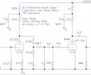
Can someone tell me if I'm correct that the anode load resistor is the 1000k from the schematic and the +B dropper is the 12k. I'm having some trouble finding a 12k resistor that's 9watts or higher. How critical is that exact value?Power rating, all resistors are fine as 0.5W excepting the Anode Load and +B dropper resistor for the Output Stage. They needs to be 3W & 9W minimum
Step up transformer for this phono preamp ?
Hi, I´m about to build this phono preamp, however I need to get at least two volts out of it (my main amp is 1.5 watts and my speakers are only 87db efficient, so I really need those 2 volts to get satisfying listening levels).
To get those 2 volts I was planning on using a 1:4 step up transformer. My amp has an input impedance of around 250k (baxandall tone control input (yes I like tone controls, so what 🙂) so, 250k/16 = 16k which, for what i've read here should be fine for this preamp.
I´m in argentina, the only kind of decent quality transformers I found here are the neutrik ones, but the only one which seems to fit the design is this one, which has been designed for MICs (Neutrik - Audio - Transformers - NTM4)
Another option, if the neutrik are not adequate, would be to contact lundahl and ask them to send me the right transformers.
My questions :
1- Would the neutrik 1:4 mic transformer be adequate for this design ?
2- If not, which do you think would be the most adequate lundahl transformer to get the 0,5v to 2v ?
Thank you very much for any help you can provide me.
Hi, I´m about to build this phono preamp, however I need to get at least two volts out of it (my main amp is 1.5 watts and my speakers are only 87db efficient, so I really need those 2 volts to get satisfying listening levels).
To get those 2 volts I was planning on using a 1:4 step up transformer. My amp has an input impedance of around 250k (baxandall tone control input (yes I like tone controls, so what 🙂) so, 250k/16 = 16k which, for what i've read here should be fine for this preamp.
I´m in argentina, the only kind of decent quality transformers I found here are the neutrik ones, but the only one which seems to fit the design is this one, which has been designed for MICs (Neutrik - Audio - Transformers - NTM4)
- NTM4
- Professional studio transformer for PCB mount, fully shielded.
- Studio transformer Mic 1:4
- Impedance ratio: 200:3.2k
- Source/load impedance in Ohm: 200/10k
- Max. Input level (@ 50 Hz, 1% THD): +9 dBu
- Applications: mic input step-up
Another option, if the neutrik are not adequate, would be to contact lundahl and ask them to send me the right transformers.
My questions :
1- Would the neutrik 1:4 mic transformer be adequate for this design ?
2- If not, which do you think would be the most adequate lundahl transformer to get the 0,5v to 2v ?
Thank you very much for any help you can provide me.
Hi,
What cartridge are you using?
You need a transformer that would be specified as 10K:80K, mu metal shielded. Not a lot of options, if any... I doubt most that you can actually get would be that good...
No.
Lundahl does not have any adequate item in their catalog.
For what you need you may get more mileage out of a 2nd stage with ECC83, use with 100K load and in griedleak bias. This should get you most of the way, with your high impedance amplifier input the 6DJ8 is not needed, if you can make sure the cable is low capacitance.
Ciao T
Hi, I´m about to build this phono preamp, however I need to get at least two volts out of it
What cartridge are you using?
To get those 2 volts I was planning on using a 1:4 step up transformer. My amp has an input impedance of around 250k (baxandall tone control input (yes I like tone controls, so what 🙂) so, 250k/16 = 16k which, for what i've read here should be fine for this preamp.
You need a transformer that would be specified as 10K:80K, mu metal shielded. Not a lot of options, if any... I doubt most that you can actually get would be that good...
1- Would the neutrik 1:4 mic transformer be adequate for this design ?
No.
2- If not, which do you think would be the most adequate lundahl transformer to get the 0,5v to 2v ?
Lundahl does not have any adequate item in their catalog.
For what you need you may get more mileage out of a 2nd stage with ECC83, use with 100K load and in griedleak bias. This should get you most of the way, with your high impedance amplifier input the 6DJ8 is not needed, if you can make sure the cable is low capacitance.
Ciao T
Hi, thanks for answering.
The turntable is a clearaudio concept with an output of around 3.5 mV.
About the mod to the circuit, you mean something like this ? I just replaced the 1m resistor for a 100k one and the ecc88 for an ecc83.
Should the other resistors remain the same ? and the 2u2 cap should remain this value ?
Thanks
Attachments
Last edited:
Hi, thanks for answering.
You mean something like this ? I just replaced the 1m for 100k and the ecc88 for ecc83.
Should the other resistors remain the same ? and the 2u2 cap should remain this value ?
Thanks
You mean something like this ? I just replaced the 1m for 100k and the ecc88 for ecc83.
Should the other resistors remain the same ? and the 2u2 cap should remain this value ?
Thanks
Hi,
The 12K on the Anode become 100K, the 1M stays as is, the 2.2uF can be a lower value, I would no go below 0.47uF.
Ciao T
About the mod to the circuit, you mean something like this ? I just replaced the 1m resistor for a 100k one and the ecc88 for an ecc83.
Should the other resistors remain the same ? and the 2u2 cap should remain this value ?
The 12K on the Anode become 100K, the 1M stays as is, the 2.2uF can be a lower value, I would no go below 0.47uF.
Ciao T
- Home
- Source & Line
- Analogue Source
- DC phono