Nope. I was mulling this over yesterday, but hadn't got round to drawing the picture yet.Wow, you whip these things up in an instant!
Probably very well. That's (part of) what John Curl used in the Blowtorch preamp. His reason was that the smaller cap values allowed him to use good plastic film caps, instead of electrolytic.I wonder how a fet based version would work, in keeping with the overall theme of this design?
edit: The high output impedance of the FETs meant he ended up using separate regulators for every stage of both channels. That was just the final stage of regulation, too!
Sometimes it's hard to make sense of audiophile lore. e.g. It seems to a classic case of doublethink to simultaneously believe:...the supposed sonic penalty of capacitors...
A) Any capacitor in the signal path severely degrades the sound quality, and
B) Valve amps sound great,
given that valve amps generally have more caps in the signal path than you can shake a stick at.
I'll think about the rest and try post later.🙂
Last edited:
Swordfishy.
Look at the multiplier.
Imagine for this first thought process that no output current is flowing.
Vc3 = Vc4 = Vc2 - VbeQ1
Vc2 = 33/34 * Vc5
With pure DC (no ripple) you can determine the output voltage relative to the input voltage.
Now assume the multiplier is perfect.
Add some ripple to the Vc5.
If you decrease the voltage on C5 so that VceQ1 < VbeQ1, then the multiplier transistor is becoming saturated and the multiplier action is becoming steadily worse. Much worse.
You can predict when the Vce < Vbe by looking at that 33/34 (R1 & R2) ratio.
In the general case (not perfect multiplier action)
If the ripple causes +-2% variation on C5 then the multiplier works.
If the ripple is less than +-1% variation then the multiplier works better (because the hFE is higher).
If the ripple exceeds +-3% variation on C5 then the multiplier becomes nearly useless. (because hFE approaches single digit values).
If you want your multiplier to be effective with a high ripple input then you increase that 1k:33k to 1k2:33k or 2k:33 etc.
What you must avoid, for effective multiplier action, is the voltage on the collector of Q1 approaching the voltage on C2.
Last edited:
Thanks Andrew, I understand what you're saying and I can see that you're right. I'm not sure I want to go the cap multiplier route anyway and to be honest I really like the idea of a simple CRCRCRC filter for the input stage. It seems more in line with the raw approach of this design.
In the meantime, I am thinking of replacing the output stage with a pair of the devices I discussed here:
http://www.diyaudio.com/forums/pass-labs/209632-triodey-transfer-curves.html
I think these devices would be a natural in a circuit like this.
In the meantime, I am thinking of replacing the output stage with a pair of the devices I discussed here:
http://www.diyaudio.com/forums/pass-labs/209632-triodey-transfer-curves.html
I think these devices would be a natural in a circuit like this.
Or just one transformer with a separate winding for each channel, and voltage doublers / triplers for the higher voltages.3) By running a single rail, I could use two off the shelf transformers (one HV and one LV) with dual windings and have a dedicated winding for each channel and almost full dual mono construction. This lightens the requirements for preventing the crosstalk you mentioned above.
You can organize effective speaker protection with a relay across the output, so the output cap charges and discharges through the relay, not the speaker.Soooo, as much as it is tempting to always go more complicated, the single rail version is looking pretty promising. The only problem is that turn on thump, which I need to go model I think.
A few words on cap multipliers.
They leverage the capacity of a smaller, high Q cap with semiconductor devices to make a larger, virtual capacitor.
Fundamental to this is the overlay of the active device transfer function on the smaller cap.
I have an uneasy feeling about this, since clearly this transfer function cannot match the very smooth transfer of a cap, even an electrolytic.
Cheers,
Hugh
Aksa,
think about it as a Zener replacing that high Q cap (C5) you refer to.
Now you have a voltage regulator using the Zener as the reference voltage and the output is dependent on the Vz and Vbe of the pass transistor.
The capacitor multiplier works in similar fashion, the output voltage is dependent on Vc5 and Vbe of the pass transistor.
The BIG difference is C5 holds the average of the input voltage, whereas the Zener tries, quite poorly, to hold a fixed voltage.
If one can design a Zener regulator to perform well in the circuit then one should be able to design a cap multiplier to perform just as well in that circuit. I think the cap multiplier is capable of better performance than the Zener regulator.
Hi Guys,
Thanks all for your input, I have been meaning to get the cap multiplier into the simulator to test it, but unfortunately have been working 12 hour days this week. Hopefully I can get into it on the weekend. One thing I have decided though is to replace my output stage with some of those mega mosfets I linked above. I'm thinking of running them at up to 50W a piece! Just cause I can 🙂
Thanks all for your input, I have been meaning to get the cap multiplier into the simulator to test it, but unfortunately have been working 12 hour days this week. Hopefully I can get into it on the weekend. One thing I have decided though is to replace my output stage with some of those mega mosfets I linked above. I'm thinking of running them at up to 50W a piece! Just cause I can 🙂
Very Nice
Well,
I finally had the chance to simulate the cap multiplier and I must say I am very impressed by the performance of such a circuit. What a great way to get a smooth supply with minimal power dissipation.
I tried it with a mosfet as the active device, but did not get very good results. The BJT is clearly superior in this application. Ultimately this is the circuit I came up with, the ripple is so close to zero it's not funny.
Any thoughts on the suitability of this circuit, and am I missing anything?
Thanks for putting me on to this, it really is a great way of doing things - non linear performance aside.
Now to see how it sims in circuit.
Attachments
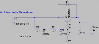
Oops, looks like my simulation parameters were wrong. With about 88v input and 4v p-p of supply ripple, it produces an output voltage of about 80v with 0.2mV p-p of ripple.
It has it's limits. Even if the base voltage is held completely constant, there will be some ripple at the output due to Early effect.
That double RC gives it a really slow rise at start-up. After 2 seconds, the output voltage is almost 1/2 way there!
That double RC gives it a really slow rise at start-up. After 2 seconds, the output voltage is almost 1/2 way there!
Who developed a few variations?
Some gave much improved performance compared to the basic.
Keantoken?
4Vpp to 0.2mVpp is 86dB of hum attenuation.
It will be slightly better for the lower mains harmonics.
Spike performance will not be as good.
Some gave much improved performance compared to the basic.
Keantoken?
4Vpp to 0.2mVpp is 86dB of hum attenuation.
It will be slightly better for the lower mains harmonics.
Spike performance will not be as good.
Last edited:
AndrewT, do you think adding a larger final cap to the multiplier will improve the spike performance?
This is the amplifier circuit I am contemplating as a final design. I think I'll stick to one pair, or maybe 3x output fets, since the cap will block any dc.
This is the amplifier circuit I am contemplating as a final design. I think I'll stick to one pair, or maybe 3x output fets, since the cap will block any dc.
Attachments

I have little idea.
Any esl in a capacitor here will certainly influence the HF output impedance.
I would be more inclined to trap spikes nearer the input.
And decouple nearer the current client.
Any esl in a capacitor here will certainly influence the HF output impedance.
I would be more inclined to trap spikes nearer the input.
And decouple nearer the current client.
Current through pots R8,9 and R33,34 ? think about using fixed value resistors with suitable wattage.
Cheers / Chris
Cheers / Chris
Cap multiplier ( in this example dual rail ) discussed here:
Capacitance Multiplier Power Supply Filter 🙂
Cheers / Chris
Capacitance Multiplier Power Supply Filter 🙂
Cheers / Chris
Current through pots R8,9 and R33,34 ? think about using fixed value resistors with suitable wattage.
Cheers / Chris
Not too worried about this, it's only a milliamp or so.
Thanks for the link - good article.
- Status
- Not open for further replies.
- Home
- Amplifiers
- Solid State
- DC offset