
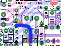
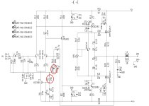
I have tried to trace the tracks on the pcb. RG is connected to the "dirty" ground and has no connection to signalground, or as you call "clean" ground.
I think that is the problem. I will try to to cut this track on the pcb for two times to eliminate this track completly.
Then cut the track at the 3 pol input to get the middle connection free, so i can use for clean /signal ground. Perhaps that the way...
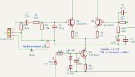
On the schematic 1/2 are different at the input for better drawing.
Greets
Peter
I think that is the problem. I will try to to cut this track on the pcb for two times to eliminate this track completly.
Then cut the track at the 3 pol input to get the middle connection free, so i can use for clean /signal ground. Perhaps that the way...
On the schematic 1/2 are different at the input for better drawing.
Greets
Peter
Attachments
What you mean? North end of the RG is considered as signal ground, south end of RG is the dirty ground.
At least in the schematic. don't know about the PC. Schematic is correct.
When using lifted ground with RG, since you have only one wire connecting PCB ground to the PSU ground, north of RG is considered 'clean ground'
and normal ground is considered 'dirty ground'.
We could say that you have 'local clean ground' achieved by lifting 'normal ground' (dirty).
Ok, then i have missunderstood. I try ones more to connect the R5, 22k, to the dirty, normal ground on the pcb, The RG will not be shorted and will hear to the amp...
Its a bit difficult for me to understand. Never heard about clean and dirty ground before , but willing to learn.
Thank you very much again..
Peter
Its a bit difficult for me to understand. Never heard about clean and dirty ground before , but willing to learn.
Thank you very much again..
Peter
My understanding of the term "lifting ground" (usually with 10 Ohm resistor) is that in the absence of proper clean ground on the PCB,
we are creating it, by "lifting" dirty ground (the only one ground present on the pcb) with a resistor.
As a result, we still have 'dirty ground' (as before), and we also have 'clean ground' (lifted).
'signal ground' = 'clean ground'
we are creating it, by "lifting" dirty ground (the only one ground present on the pcb) with a resistor.
As a result, we still have 'dirty ground' (as before), and we also have 'clean ground' (lifted).
'signal ground' = 'clean ground'
I think i got it....
What i have done...
I have measured the voltages dropping over the resistors R3/R4 and R12/R13. Not much difference but a little difference i could measure .
R3 0,058 mV, R4 0,056 mV, R12 0,812 mV, R13 0,810 mV. I soldered them out and measured a little difference between. Ok, 1% metal film resistors.
I had ordered 0,1 % metallfilm resistors and before i soldered new ones in i measured the resistors to find equal ones.
I leave RG unshorted, but made a connection from my starpoint to signalground (cleang ground) as before.
Got 1mv offset now...very fine. I haven't tested the second board in this way until yet, but i think will be the same, if i change the resistors.
Many thanks
Peter
Hi...
Its the same with the second board. Under 1 mV offset and the best news ..no hum...🙂
@BSST
The C5 is connected to R10 with its +, in all schematics, i have found, is always the same . My knowledge its too small if its wrong or right. I can measure if the base voltage is positiv or negative. If negative i can turn C5...
On my new pcb i use a Nichicon Muse 220 µf non polar. Everytime i take look to the pcb i find something to change....
Greets
Peter
Attachments

I took a little time...
I had ordered Muse non polar capacitors 1000 µf. My amp in the bigger housing is working fine...offset under 1 mV on the two boards. 🙂
But i have an Amp in a smaler smaller housing. This amp gets 20 (with starpoint connection lower than 1mV) and 26 mV offset.
If i try to make a connection to the starpoint on the board with 26 mV, the offset rises to 40 mV.
I wonder why... it is the same starpoint connection i made. It seems to be some trouble with this grounding to the clean ground, 10 ohm resistor on the board.
The boards are equal, with the same changes. R12/13/14 are 680 Ohm 0,1 %. I measured to get same value. R3/R4 are the same, 47 Ohm resistors. The voltage is identical. Matched transistors if possible. IRF240/9240 have 4,04/4,02 Vgs. The drivers are matched, KSC1845 input transistors too, as near as possible, i used the BJT Matcher.
The board with the higher offset i took out and fasten on my testboard...i can do anything, the offset remains at 26 mV and if i make the connection to signalground from the starpoint the offset rises up to 40 mV. Something is wrong....
Any ideas ?
I have one empty board left, perhaps i solder everything new.
Here the schematic again....
Greets
Peter
Attachments
Hi Chris,
R23/R24 are out of the same 0,22 Ohm series as in all 4 boards. I can try to change R8/R15 and measure the voltage...
I will make a few measurements in the next days and compare with the other board....hoping to find something unusual...
Greets
Peter
R23/R24 are out of the same 0,22 Ohm series as in all 4 boards. I can try to change R8/R15 and measure the voltage...
I will make a few measurements in the next days and compare with the other board....hoping to find something unusual...
Greets
Peter
Hi...
searching for hours...cant find any faulty component or something else...
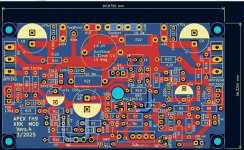
I took my last empty pcb and built a new board. This board has under 1mV offset now, using a normal electrolytic capacitor 1000µf 25 volts and i can use a connection to the starpoint. If i use a non polar capacitor the offset rises a little bit up to 2mV. Good, but not good enough. I think there is something wrong with this Muse non polar capacitor. I ordered new ones.
Peter
searching for hours...cant find any faulty component or something else...
I took my last empty pcb and built a new board. This board has under 1mV offset now, using a normal electrolytic capacitor 1000µf 25 volts and i can use a connection to the starpoint. If i use a non polar capacitor the offset rises a little bit up to 2mV. Good, but not good enough. I think there is something wrong with this Muse non polar capacitor. I ordered new ones.
Peter
Attachments
Fine, i have 220 µf 25 Volt in Stock. Muses green ones...i test it out.
You are right, soldering the Capacitor as marked on the pcb get negativ voltage the base of T2.
Thanks
Peter
You are right, soldering the Capacitor as marked on the pcb get negativ voltage the base of T2.
Thanks
Peter
I get the best result with the black Muse 1000 µf 25 Volt. 2 mV offset. I will live with it, spending no more time with searching. Its sure better as the 40 mV i had before, with a connected signalground. I spend too much time to get a better result. I will hear no diiference if 1mV or 2 mV.
Without a DC servo its very good.
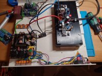
I assembeld this compact modell of an amp and have to adjust the bias on one board.
@BSST you are right, if i turn the feedback capacitor, i can get a positive or negativ offset, tested with a normal electrolytic capacitor. Different voltages, positiv or negativ on the base of T2.
Thanks to all for helping
Peter
Without a DC servo its very good.
I assembeld this compact modell of an amp and have to adjust the bias on one board.
@BSST you are right, if i turn the feedback capacitor, i can get a positive or negativ offset, tested with a normal electrolytic capacitor. Different voltages, positiv or negativ on the base of T2.
Thanks to all for helping
Peter
Attachments

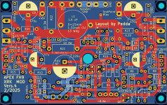
Hi Peter, would you mind sharing the kicad or gerber file for your latest Apex FH9 layout?Hi...
Its the same with the second board. Under 1 mV offset and the best news ..no hum...🙂
@BSST
The C5 is connected to R10 with its +, in all schematics, i have found, is always the same . My knowledge its too small if its wrong or right. I can measure if the base voltage is positiv or negative. If negative i can turn C5...
On my new pcb i use a Nichicon Muse 220 µf non polar. Everytime i take look to the pcb i find something to change....
Greets
Peter
Thanks for your work on this!
Geno
Attachments
- Home
- Amplifiers
- Solid State
- DC Offset too high at my FH9 XRK Mod