Hi....
First i soldered out R5, 22k on one side, soldered a little wire on and soldered the end of R5 to dirty ground. No success....-20 mV offset
I see that the output is now negative with about -20 mV. I wonder why. The only change i made was to change the 47 ohm resistors, R3/R4 to 0,1 % and used new matched drivers. I could notice that 0,1 % resistors will lower the offset a little bit more. Soldered 1% again in. I odered MPR 0,1% resistors for all input resistors.
Second try with shorted RG, 10 ohm....very low offset, about -2,4 mV. But the output voltage is not stable, its floating a little bit, wents between -3 mv and 1,5 mV up and down. Is this normal ? I have no load at the output, input is shorted.
I will short RG on the second board, adjust the bias and test the amp with speakers. hoping to get no hum.
Greets
Peter
Second try with shorted RG, 10 ohm....very low offset, about -2,4 mV. But the output voltage is not stable, its floating a little bit, wents between -3 mv and 1,5 mV up and down. Is this normal ? I have no load at the output, input is shorted.
yes its normal. its the thermal issue in the amp...(bias Spreader T0-126, BD139)
keep that!
yes its normal. its the thermal issue in the amp...(bias Spreader T0-126, BD139)
keep that!

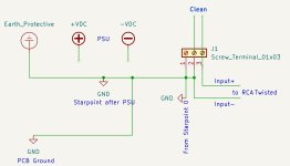
I try to avoid lifted ground. Instead i usually have 2 separate grounds on the pcb: dirty and clean. They are not connected on the pcb, but there are 2 separate wires, from each of the grounds to the common ground point - usually close to the psu ground.
Meanwhile...Bias adjusing the ...forgotten to count...🙂
The second board got 1,0 mV offset.
The second board got 1,0 mV offset.
If i understand right, you set a starpoint near the psu output. One wire to the PCB ground, 0, and one wire to the signal ground, RCA and pcb input ?
How does it sound?
I tried to build 2 amps in the past - with hexfet outputs and no drivers, but they did not sound good.
They simmed ok, and measured ok on the oscilloscope, but the sound was bad...
From what I see, hexfet amps need drivers....
I tried to build 2 amps in the past - with hexfet outputs and no drivers, but they did not sound good.
They simmed ok, and measured ok on the oscilloscope, but the sound was bad...
From what I see, hexfet amps need drivers....
Correct, but not exactly.If i understand right, you set a starpoint near the psu output. One wire to the PCB ground, 0, and one wire to the signal ground, RCA and pcb input ?
1 GND wire to dirty ground on the pcb.
1 GND wire to clean ground on the pcb.
RCA connectors are not grounded to the case. Twisted pair wires connect RCA to the PCB (using clean ground obviously).
I get better results (no hum!) using twisted pair wires rather than shielded cables.
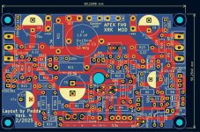
Note twisted pair wires for inputs.
Arrow points to the 'clean ground' connection. Dirty ground is somewhere closer to the output.
All wires, including gnd, are soldered under the PCB.
Last edited:
RCA connectors are never grounded to my cases...clear...
I can understand dirty gound, what please, Sir, is dirty ground ? Dirty ground= signal ground ?
I can understand dirty gound, what please, Sir, is dirty ground ? Dirty ground= signal ground ?
'dirty ground' is 'output ground' where flowing currents are higher.
Everything except what mentioned below, should be connecting to dirty ground.
'clean ground' is ground with minimal currents, where only input LTP stuff is connected to.
Normally that would be only stuff connected to the BASES of the LTP
keyword 'dirty' means that currents flowing through that ground are higher, and fluctuating widely (e.g. from rail caps).
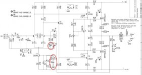
in your case, only C2, R2, C4, C5 should be connecting to the clean ground. And of course the input wires going to RCA jacks.
Everything except what mentioned below, should be connecting to dirty ground.
'clean ground' is ground with minimal currents, where only input LTP stuff is connected to.
Normally that would be only stuff connected to the BASES of the LTP
keyword 'dirty' means that currents flowing through that ground are higher, and fluctuating widely (e.g. from rail caps).
in your case, only C2, R2, C4, C5 should be connecting to the clean ground. And of course the input wires going to RCA jacks.
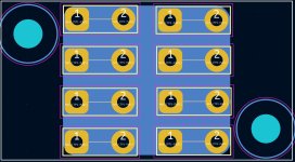
I had made little pcb's for a starground/starpoint. I will test your advice.
I can set the small pcb in front of the spms and connect all grounding wires with fast on, or solder wires on. Now i have understand what do mean with dirty and clean ground.... 🙂
I can set the small pcb in front of the spms and connect all grounding wires with fast on, or solder wires on. Now i have understand what do mean with dirty and clean ground.... 🙂
Attachments
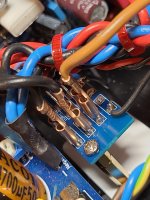
I was not lazy....builded a starground in the FH9. Clean and dirty ground have their own wires now, also speaker minus. RCA with twisted wires as you like it...there two wires from the smps to the little pcb. Only ground wires on it.
I need a 100 ohm resistor 3 watt and will connect the PE and ground with the resistor, not directly, or i use a loop breaker for PE as Elliot shows.
Greets
Peter
I need a 100 ohm resistor 3 watt and will connect the PE and ground with the resistor, not directly, or i use a loop breaker for PE as Elliot shows.
Greets
Peter
Attachments
Last edited:
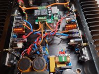
I have to test the Amp with the new connections in the next days.
But with higher offset before, the sound was very good., like it very much, my friends too...
That is the reason for me to build one more with new pcb.
I have done a few little changes with KiCad and thinking now..its finished
Greets
Peter
But with higher offset before, the sound was very good., like it very much, my friends too...
That is the reason for me to build one more with new pcb.
I have done a few little changes with KiCad and thinking now..its finished
Greets
Peter
Attachments

Hi,
today i tested the amp. I get hum out of the speakers, nothing to do with the loop breaker or clean ground wires. I think the reason is the shorted RG.
I will change back and hear if the hum will disappear with the 10 Ohm resistor, as before.
I have ordered new pcb's according to schematic 2, but i will take time to ship and deliver from china.
Other ideas ?
Regards
Peter
Just my opinion - an amp with well laid out PCB and input and ground connections/wires, will not hum.
Lifted ground is kind of cheating - like lipstick on a pig 🙂
But I guess it's still the easiest thing to do: use lifted ground (10 Ohm resistor), and connect R5 to dirty ground.
Otherwise it's a choice: you can have hum or you can have DC offset 🙂
Lifted ground is kind of cheating - like lipstick on a pig 🙂
But I guess it's still the easiest thing to do: use lifted ground (10 Ohm resistor), and connect R5 to dirty ground.
Otherwise it's a choice: you can have hum or you can have DC offset 🙂
A new idea. One RG pin has connection to ground. I solder one led pin on. Take one pin of R5, 22k, out and with a short wire a make a connection to the second led pin. Thats what is shown in the second schematic, but the pcb doesn't fit the compnents, i need, right.
I can lower the feedback capacitor, perhaps i can use a NP type. Another test then....
Peter
I can lower the feedback capacitor, perhaps i can use a NP type. Another test then....
Peter
Attachments
- Home
- Amplifiers
- Solid State
- DC Offset too high at my FH9 XRK Mod