I know this is car amplifier, but beside the inverter it is a solid state.
Before i use tda2050 with 24v dc ct inverter in my car, no pcb i solder the resistor and caps straight to the pin as short as posibble. Sounds good, but it is hot and i think it have potential fire hazard.
So, i buy this cheap amplifier and replace most component with a better one. This is what i do:
1. Change all the 1/8w carbon resistor with 1/4w metal film.
2. Replace original capacitor to better capacitor. i use elna re3, silmic ii and panasonic fc. For smaller value i replace mylar with generic mkm and philips mkt. I replace mono ceramic with 2kv ceramic.
3. Replace the original jrc4458 with original ne5532 from ti. Yes, they got both input protected with transistor configured as diode.
4. Change supply for opamp from zener with lm7815 and 7915. I measure the voltage at +15.1v and -14.8v. I use two 220ohm 2wa resistor in parallel before the regulator.
5. Rewind the inverter toroid from 24v to 32v. Replace the original pair of 4700uf 35v capacitor with 10.000uf 50v+1000uf.
6. Add another gain stage before the amplifier with resistor divider at the input, i use ne5532 set around 9x gain. I use shielded cable around 10cm, i also ground the shielding wire. The total gain is around 2.5x. i do this because the source voltage output is to low, if i increase the volume i notice distortion using 50hz test tone.
7. Change the final transistor on the channel that i use for my woofer and tweeter. Before it was 2sc5198/a1941, i replace it with 2sc5200/a1943. It got 2 way passive crossover.
It works, no noise albeit a little muddy. Maybe because i use elna silmic which need some burn in period. And yes, i know it is improper using electrolite as input caps, but i like it. The original caps is generic eletrolite anyway, so it might be an improvement.
The problem is, i got 120mv dc offset on one ch. The other 3 was below 20mv measured. On this ch i use the original final transistor, it was the 2sc5198/a1941. I recheck all the resistor value, nothing wrong. I also resolder all the solder joint. The one thing i notice is 0.01v diffrence between the base of the 2sc5198/a1941.
Did i miss something? Do the 0.01v diffrence between the final transistor pair base is the problem or should i look somewhere?
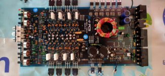
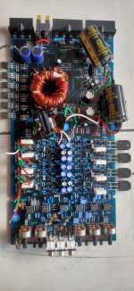
Here i attach the before and after pic. i add the gain stage later on and is not in the after pic, it was before hf filter on the amplifier input(it was 2.2k resistor with 100pf to ground, the input resistor is 10k):
Before i use tda2050 with 24v dc ct inverter in my car, no pcb i solder the resistor and caps straight to the pin as short as posibble. Sounds good, but it is hot and i think it have potential fire hazard.
So, i buy this cheap amplifier and replace most component with a better one. This is what i do:
1. Change all the 1/8w carbon resistor with 1/4w metal film.
2. Replace original capacitor to better capacitor. i use elna re3, silmic ii and panasonic fc. For smaller value i replace mylar with generic mkm and philips mkt. I replace mono ceramic with 2kv ceramic.
3. Replace the original jrc4458 with original ne5532 from ti. Yes, they got both input protected with transistor configured as diode.
4. Change supply for opamp from zener with lm7815 and 7915. I measure the voltage at +15.1v and -14.8v. I use two 220ohm 2wa resistor in parallel before the regulator.
5. Rewind the inverter toroid from 24v to 32v. Replace the original pair of 4700uf 35v capacitor with 10.000uf 50v+1000uf.
6. Add another gain stage before the amplifier with resistor divider at the input, i use ne5532 set around 9x gain. I use shielded cable around 10cm, i also ground the shielding wire. The total gain is around 2.5x. i do this because the source voltage output is to low, if i increase the volume i notice distortion using 50hz test tone.
7. Change the final transistor on the channel that i use for my woofer and tweeter. Before it was 2sc5198/a1941, i replace it with 2sc5200/a1943. It got 2 way passive crossover.
It works, no noise albeit a little muddy. Maybe because i use elna silmic which need some burn in period. And yes, i know it is improper using electrolite as input caps, but i like it. The original caps is generic eletrolite anyway, so it might be an improvement.
The problem is, i got 120mv dc offset on one ch. The other 3 was below 20mv measured. On this ch i use the original final transistor, it was the 2sc5198/a1941. I recheck all the resistor value, nothing wrong. I also resolder all the solder joint. The one thing i notice is 0.01v diffrence between the base of the 2sc5198/a1941.
Did i miss something? Do the 0.01v diffrence between the final transistor pair base is the problem or should i look somewhere?
Here i attach the before and after pic. i add the gain stage later on and is not in the after pic, it was before hf filter on the amplifier input(it was 2.2k resistor with 100pf to ground, the input resistor is 10k):
Attachments
It is hard to tell anything from your photos, what I would look for is where the offset starts, is one of the opamps perhaps? I do see the IC on left bottom not pushed in properly
Don't take this the wrong way but those improvements did nothing to improve anything.
Caps don't need to be burned in.
Do you see more DC offset on the output terminals of one op-amp than the other op-amp output terminals?
Caps don't need to be burned in.
Do you see more DC offset on the output terminals of one op-amp than the other op-amp output terminals?
Sorry, forgot to tell that I notice it when i put the final transistor. Its already properly fix to position when i test it.It is hard to tell anything from your photos, what I would look for is where the offset starts, is one of the opamps perhaps? I do see the IC on left bottom not pushed in properly
Anyway the amplifier input was from the second opamp from the left and third opamp from the right.
I pull 2.2k and 2k resistor from the second(from the left) opamp output feed it to another ne5532 on separate board and put the resistor back at its output. It goes to the two amplifier i the left (the two without final transistor in the pic), before 100pf cap and 10k input resistor to ground.
For the other two i pull two 1k resistor from the third opamp from the right, feed it to another ne5532 in separate board and put the 1k resistor back at the opamp output. Then it goes to 100pf and 10k input resistor to ground.
@Perry Babin: i do notice improvement. Before i got a very audible hiss, harsh vocal and treble, and as i increase gain there is increasing distortion. And before i only measure 11.7v ac at the speaker pin at max gain now i got around 11v below half on gain pot. Now i got no noise whatsoever, it was dead silent. Sound was clear and crisp when i turn the gain until i hit clipling around 60-70%.
My aim here is to got an acceptable sound quality at a minimum expense, so far i only spent around $25. I replace 139 resistor and almost 100 caps. Usually for resistor i use vishay dale but i use yageo, here vishay dale resistor cost around $0.5 each. Those yageo and generic mkm caps cost next to nothing. The toshiba 2sc5200/a1943 was manufactured in japan and assembled in malaysia and cost me $1.5 per pair, Ne5532 at around $0.5 a piece.
I do not want to start cap and burn in debate, but i once test an old(been used about a year) and new tda2050 with exact same component even the heatsink bought from same source. On blind test two crowd agree the older sounds better than the new one. I use the same psu and speaker in this "audition". I do not think it was the resistor, solder, wires or the tda2050. So my suspect is the electrolite caps might need some burn in, just maybe.
Also, once i replace 1uf silmic ii with kemmet mkt, because i read that film cap was better than electrolite for input decoupling. I felt the sound clean but rather dry using kemmet mkt. In the end i put the old silmic back, for me it sound better. Maybe just my imagination, but i do notice slight but acceptable distortion with silmic as input cap.

Hi Widh61,
Listen, I have to agree fully with Perry on this. There are things you can do to improve quality but not what you have done so far.
Those main filters need to be soldered in place like the originals. If they don't fit, drop the capacitance until they do. You can't use parts that don't fit. By hanging them on leads you have created issues you didn't have before. Lose the darned sockets! They increase capacitance between the leads for one.
Did you check for oscillation on the outputs? Meters can respond in odd ways to RF signals, or it the RF is distorted it will be an effective DC offset, but not for the reasons you think. So, you absolutely do need an oscilloscope here. You also really need a THD meter, or better yet an audio analyzer. Disagree or not, but there are very good reasons why we purchase and use this expensive equipment. Wouldn't be great if we just had to use our professional, tuned hearing ('cause we do this for a living)?
One thing about testing listening to music. People make terrible test instruments! Very unreliable. Very susceptible to whatever is in their head and cues from others in the area.
I would listen to Perry if I were you.
-Chris
I will try both of your suggestion. The reason i use socket is because i am not sure ne5532 will work because it bipolar vs the jfet on jrc4558. The resistor range are around 1k to 150k and the resistance between +/-input and output is between 1k to 30k, which i believe ne5532 might work.
When i get home i will remove those socket and wires, i will drill directly on the pcb. It surely wont fit on the case but just for testing. I also will check dc on opamp output. I check it before but i will recheck just in case. Anyway, thanks for both of you.
When i get home i will remove those socket and wires, i will drill directly on the pcb. It surely wont fit on the case but just for testing. I also will check dc on opamp output. I check it before but i will recheck just in case. Anyway, thanks for both of you.
Hi,
The 4558 is an improved 741 type op amp, BJT diff pair. Same as the 5532A. The 5532 is a vastly better part, not just an improved 4558 or 741 type.
You need to examine what is going on using an oscilloscope. Trial and error is not the answer.
The 4558 is an improved 741 type op amp, BJT diff pair. Same as the 5532A. The 5532 is a vastly better part, not just an improved 4558 or 741 type.
You need to examine what is going on using an oscilloscope. Trial and error is not the answer.
So, with a borrowed meter from a friend. I found 3mv on the third opamp from the right, it is on pin 5. My meter only read 1mv. Then i soldered two 100nf ceramic cap from pin 4 and 8 to ground patch in the middle op the opamp. Dc still there. I then replace the opamp with jrc4558, got no dc. I got 17mv on the speaker terminal.
Do i got defective chip or is it the resistor capacitor combination on the input?
I notice that the second opamp from the left, left side configured as non inverting with gain of 10 with 3k and 27k resistor. The right side configured as inverting with 15k and 150k resistor also at gain of 10. Why they do that? Is it posible that inverting/non inverting configuration affect stability of the opamp?
Hold on now!
Listen to what I said earlier. If something is oscillating and has distorted output, you will see an effective DC offset. However meters all respond differently to this, so you know nothing yet. You absolutely do require the use of an oscilloscope to see what is going on. You can't even begin to troubleshoot without knowing what is going on.
So, stop. Figure out who can help you probe various points to see what output you actually do have. You need the use of an oscilloscope, this is why they make this instrument and why it is a very basic piece of test gear on every service bench for electronics.
I'm not trying to be hard on you. In fact I am trying to make your life easy.
Okay, i try looking for a scope. Which one do i need, any recommendation? Actually i have it in my wishlist, but i am confused which one i should get. Other than for audio i might need it for like reading pwm to drive motors, and maybe for arduino.
What specs do should i look for? A good one might cost a fortune, but if i bought the cheaper one i am afraid in the future i need to buy better one or it might break somehow. Here a scope starts from $90 to around $900 and maybe more.
What specs do should i look for? A good one might cost a fortune, but if i bought the cheaper one i am afraid in the future i need to buy better one or it might break somehow. Here a scope starts from $90 to around $900 and maybe more.
For most things, ana analogue scope is the best. 100 MHz dual trace should be fine, Philips were very good as well as other brands.
If you go digital it will be expensive. You need 5x the bandwidth for starters, 12 bit preferred. I had to get a Keysight MSOX3104T (500 MHz would have been okay) to do what I needed. Looking at a CD eye pattern is impossible with less. So that was heart stoppingly expensive - and it is out for service again.
So while that thing is out, I am using my Philips PM3365A again. 100 MHz dual trace. The Keysight is better except when looking at detail in an eye pattern. The analogue wins out then.
Now if you need the digital features, like me, it means two scopes on your bench (an analogue and a digital) or an expensive digital. Keep in mind that digital scopes can lie to you. You have to be very aware of settings in case of aliasing. Keysight is more free from this than the less expensive brands. If you look up what mine is worth, you'll take the two scope route. Keep in mind that digital scopes have significant differences to analogue ones, and beyond the whiz-bang features, the waveform is much better with analogue.
-Chris
I cannot find either keysight or philips, i might need to buy them from overseas.
The one avaliable in my local marketplace with 100mhz dual channel and 1gsa/s is:
For analog there is:
I think i will suspend this project till i got a scope. Now i got opa2604 replacing jrc4558. Currently i only have tl072, jrc4558 and opa2604. I will ground both the opamp input, remove the jumper feeding the amplifier input and ground it. I willl also pull the final transistor. Then i am gonna paralel the final transistor to feed my subwoofer at 2ohm, driving the sub at 2 ohm with just a pair of final transistor was too hot.
For similar specs the analog was significantly more expensive, i am considering the digital fnirsi or hantex. I limit my budget at around $250.
The one avaliable in my local marketplace with 100mhz dual channel and 1gsa/s is:
- Hantek DSO5102P at $250,
- fnirsi 1013D at $140 and
- rigol DS1102E at $470. The most popular one was the hantek scope.
For analog there is:
- aditeg os620 at $240, 20mhz 5x
- sanfix sos620 at $280, 20mhz 10x
- twintek tos2020ch at $255, 20mhz 10x
- gw-instek gos 620 fg at $640, 100mhz 10x
- b&k precision 2190b at $330, 100mhz
I think i will suspend this project till i got a scope. Now i got opa2604 replacing jrc4558. Currently i only have tl072, jrc4558 and opa2604. I will ground both the opamp input, remove the jumper feeding the amplifier input and ground it. I willl also pull the final transistor. Then i am gonna paralel the final transistor to feed my subwoofer at 2ohm, driving the sub at 2 ohm with just a pair of final transistor was too hot.
For similar specs the analog was significantly more expensive, i am considering the digital fnirsi or hantex. I limit my budget at around $250.
b&k precision 2190b is a good scope.
I can't stand to use a digital scope. Too many have a Donkey Kong display and can't display a smooth line. I worked for 30 years and virtually never needed anything that an analog scope couldn't do. A digital scope will make you lazy and dependent on features that you don't need for audio repair.
I can't stand to use a digital scope. Too many have a Donkey Kong display and can't display a smooth line. I worked for 30 years and virtually never needed anything that an analog scope couldn't do. A digital scope will make you lazy and dependent on features that you don't need for audio repair.
Hi Perry,
Completely agree with you on most points. Although if you're lazy with a digital, it is busy lying to you! You have to be more aware with a digital scope, especially the cheaper ones.
I needed some of the triggering features on the Keysight, plus it will capture a waveform and play it back (or you can export it to an arb). Then there are the 16 digital channels time aligned with the analogue channels. I can correlate control signals to analogue happenings. This has been a life saver in my work.
In short, for most audio work, a good analogue scope is exactly what you do need. An inexpensive digital scope is precisely opposite and will fight you.
-Chris
Hi. Had possibility to repair something similar , a cheap car amplifier , 4 ch , had large dc offsets too , and output amplifiers were ok . Problem was tl074 if i remember correctly, had random high dc offsets at outputs. Final amplifiers had direct input connection from diff stage to tl074 , no ac coupling capacitors, but feedback had electrolytic cap. So a 0,7v dc from opamp had transferred to spkr terminal as 0,7v. Problem solved by replacing all the ic's . Audio ic mostly are not low offset ones, so its normal to see a several millivolts at their output with dual supply .Try to excahge ic's, they are in sockets anyway , and see how dc offset changes at spkr terminals , maybe you have similar issue.
I do not have dc offset problem anymore with either jrc4558 or opa2604. I even connect a small speaker, its working nothing abnormal, even the magnet is cold to touch. But, I think I do not need 4ch, 2.1 would be better suited for my speaker configuration.
I do need the scope for other things, it is for commercial use.
I have contacted the seller for b&k precision, got no reply atm. I am not sure with the seller. His store mostly sell clothes, i google around and find that the b&k scope should be around $1500.
I think I might spent a bit more for a good scope. I should think more throughly about this, it will be a significant investment for me.
Any of the analog scopes you listed, in good working order, will be good enough. Any 2ch, 20mHz scope will easily be good enough. The following link shows what a 2mHz scope looks like vs a 100mHz scope. The $1500 price for the 2190 was likely new. The 2120B was also popular. If you can find a used one for about $200-300 that would be a good deal.
https://www.bcae1.com/repairbasicsforbcae1/repairbasics.htm#scope
https://www.bcae1.com/repairbasicsforbcae1/repairbasics.htm#scope
Hi,
Perry is right. Most good 100 MHz dual trace scopes sell $200 ~ $300 USD. These are more than good enough.
Some, like the Philips PM3365A offer some other helpful features while also working as a pure analogue scope. The trace is very sharp on Philips and these would make great choices. Probably easy to get in your area.
-Chris
@Perry:
Yesterday, i watch several youtube video comparing analog vs digital. Beside the first one i watched comparing a digital keysight priced close to $2000 to an tektronik analog, all point out that analog was better.
One guy comparing a digital gw-instek, an analog leader and an analog read out kenwood actually selling them. He is in my area. The digital was sold, and he want $40 for the leader and kenwood. The leader scope was a 20mhz one. If 20mhz was enough, I think this is a good deal.
If i could get the leader scope for just $40, i think I also want a cheap portable digital for $110. The only diffrence with a desktop on the same brand is on two function that i think i do not need. I will contact the youtube guy if it is still avaliable.
@anatech:
I could not find philips scope in my area.
- Home
- General Interest
- Car Audio
- DC offset problem