I have a challenge to heat 4 tubes 6SN7 with DC. I have a 6.3 VAC winding on my main transformer @ 10 Amps.
If I rectify the 6.3 VAC I don't get enough DC with the 2.4 Amp load (4 tubes). I tried a voltage doubler with 22000 uF capacitors instead, but still get only 4 VDC.
What are my options to get 6.3 VDC from this transformer? Space is very tight, so I need something very compact.
Regards, Gerrit
If I rectify the 6.3 VAC I don't get enough DC with the 2.4 Amp load (4 tubes). I tried a voltage doubler with 22000 uF capacitors instead, but still get only 4 VDC.
What are my options to get 6.3 VDC from this transformer? Space is very tight, so I need something very compact.
Regards, Gerrit
Too small diodes, too small capacitor. Could be both. And/or too small transformer.I have a challenge to heat 4 tubes 6SN7 with DC. I have a 6.3 VAC winding on my main transformer @ 10 Amps.
If I rectify the 6.3 VAC I don't get enough DC with the 2.4 Amp load (4 tubes). I tried a voltage doubler with 22000 uF capacitors instead, but still get only 4 VDC.
What are my options to get 6.3 VDC from this transformer? Space is very tight, so I need something very compact.
Regards, Gerrit
Why?If I rectify the 6.3 VAC I don't get enough DC with the 2.4 Amp load (4 tubes).
6.3VAC with a quad of Schottky diodes (e.g. SB520/30/40) will give you almost 8VDC (probably even more, considering you're using just a fraction of winding's nominal current, so the AC voltage should be higher than 6.3V). That's even enough for some CRC filtering.
Here's my take on it:
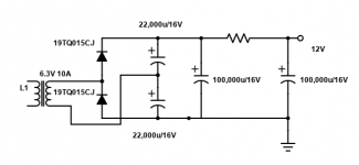
Connect pairs of 6SN7 in series and use a Delon like this. (The capacitor sizes are large - probably unnecessarily large)
The diodes are 15V Schottky and have a very low Vf.+
Use a resistor to adjust final voltage or use a MIC29300-12WT. 12V 3A regulator (Cheaper than the second large cap, too).
https://www.mouser.ca/datasheet/2/268/MIC2915x_30x_50x_75x_High_Current_Low_Dropout_Regu-1889172.pdf
Koda
Attachments
Last edited:
Hi Koda,
I’m using your diagram, however with normal diodes and without the 100000 uF capacitors.
I’m just getting 4 VDC with 2.4A load.
Do you think the extra capacitors and the Schottky diodes instead of normal ones will make the difference?
If so I could try too with a standard bridge for 6.3 VDC output? This way I wouldn’t have to change wiring for series heaters.
Regards, Gerrit
I would say if you only get 4VDC what do you get with no load? You should have almost 17VDC from a 6V doubler... If you get almost 17V, your caps are too small and the diodes drop too much. If you only get around 8V, it's not doubling.
If you use 4 Schottky diodes as a bridge with large capacitance, it should provide 6VDC or more.
If you have the time to wait - this is a nice solution: DIY PCB Board - Tube Amp - LV Tube Heater DC Power Supply - 6.3VDC from 6.3VAC | eBay[/url
Realistically, the hassle and expense of linear DC for heaters is why I now almost always use 12V SMPS for heat. 🙂
Without load I got around 17 VDC, but the voltage drop when loaded is excessive.
I just ordered some extra capacitors and schottky diodes.
Perhaps I will add a regulator, like on the DIY PCB Board you mentioned.
To be continued...
Regards, Gerrit
I just ordered some extra capacitors and schottky diodes.
Perhaps I will add a regulator, like on the DIY PCB Board you mentioned.
To be continued...
Regards, Gerrit
That is the most practical and economical solution. Getting high current DC from rectified low voltage is a real pain, and requires huge expensive smoothing capacitors, besides the stress it puts on the transformer's secondary.kodabmx said:Realistically, the hassle and expense of linear DC for heaters is why I now almost always use 12V SMPS for heat. 🙂
Chances are an SMPS would fit where the 6V transformer was LOL.
I was talking about when I design it myself. FWIW, I'm using 6 4700uF caps for smoothing a linear PS in an amp that needs over 5A. It's smooth enough that there is no hum audiable. As I said 100000uF is excessive but it would work with very low ripple 😛
I was talking about when I design it myself. FWIW, I'm using 6 4700uF caps for smoothing a linear PS in an amp that needs over 5A. It's smooth enough that there is no hum audiable. As I said 100000uF is excessive but it would work with very low ripple 😛
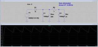
R2 is 1ohms, as in the schematic. Rht is a single 12AX7 at 0.3A, and Rfan is a 12V computer fan for cooling.
Better put the heaters two by two in series.Then you need 12,6V and 1,2A.Less loss of the diodes and smaller electrolytics.
Mona
Mona
I would say if you only get 4VDC what do you get with no load? You should have almost 17VDC from a 6V doubler... If you get almost 17V, your caps are too small and the diodes drop too much. If you only get around 8V, it's not doubling.
If you use 4 Schottky diodes as a bridge with large capacitance, it should provide 6VDC or more.
If you have the time to wait - this is a nice solution: DIY PCB Board - Tube Amp - LV Tube Heater DC Power Supply - 6.3VDC from 6.3VAC | eBay[/url
Realistically, the hassle and expense of linear DC for heaters is why I now almost always use 12V SMPS for heat. 🙂
I happened to buy one of these to evaluate on an EL84 SEP amp (1.8A for heater requirement).
The design looks mostly like I'd expect, but I was wondering if you had any insight on the use of the 15KuF on the output of the regulator ? The datasheet spec's 10uF, while the Tubelab SE-II has 4700uF on the output.
6.3 v in parallel is 2.4A, in series 12v 1.2A..
6.3v x 2.8 = 17.64vdc with capacitor unloaded, so if you are getting just 4 volts, then you got it wired incorrectly ...and any resistance you use in series will drop the voltage some more as indicated in your drawing, you can adjust the value to get closer to 12v, my guess is about 1 ohm 5 watt or thereabouts...
6.3v x 2.8 = 17.64vdc with capacitor unloaded, so if you are getting just 4 volts, then you got it wired incorrectly ...and any resistance you use in series will drop the voltage some more as indicated in your drawing, you can adjust the value to get closer to 12v, my guess is about 1 ohm 5 watt or thereabouts...
Hi Gerrit
Try the big diodes from an old computer supply. I tested one, a sbl6040, at 3 amp the voltage was 0,35.
Try the big diodes from an old computer supply. I tested one, a sbl6040, at 3 amp the voltage was 0,35.
- Home
- Amplifiers
- Tubes / Valves
- DC heater challenge