MPJA has some buck converters which work well -- SZBK07 Step Down Buck Converter | MPJA.COM
When using only 6.3VAC a step up converter could be needed. Time will tell...
Regards, Gerrit
I am using this "buck-boost" converter in one of the lab setups.
Buck-Boost DC-DC Converter Wide Range | MPJA.COM
This one will only do 1A but it is sufficient to test one tube at a time:
It will be interesting to see how any of the dc/dc boards go in a heater powering application. One issue is how they manage the initial cold heater start-up current requirement - that may see some initial hiccupping, but there is a risk of stress on the module, as well as a risk of stalled operation. Another issue is the level of ACV ripple that can be accommodated with the dc/dc still providing regulated output - that may still require a substantial first filter cap value. Another issue is whether two sequential dc/dc modules, with an intermediate capacitor buffer, is of any benefit.I just ordered two Step-up Boost Converters XL6009 4A for testing.
Is the 40VDC elevation sufficiently separated from all the 6SN7 cathode voltage levels (both idle DCV levels as well as peak signal swing levels)? If a cathode voltage gets close to the 40VDC level (eg. within perhaps 10V) then the cathode-heater interface may leak a noticeable hum current (depending on the actual 6SN7 being used, and the circuit configuration).So far the AC supply for the 6SN7’s seems to work quite well, but I still get hum somewhere. Heaters are elevated (around 40 VDC), humdinger is in place with a 10 uF film capacitor from the center tap to ground.
dc coupled tube stages like the aikido and the concertina phase splitter, have another type of noise aside from hum, more like a splatering sound....that is why it is important to dc lift the heaters to make the filament dc elevated somehow....
i have made this aikido with ac heating and dc lifting of the filaments, and it was so quiet that you have to put your ears to within an inch of the speakers to hear anything...
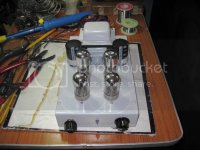
this is a 7n7 aikido with ac heating and a dc lifted filaments....
i have made this aikido with ac heating and dc lifting of the filaments, and it was so quiet that you have to put your ears to within an inch of the speakers to hear anything...
this is a 7n7 aikido with ac heating and a dc lifted filaments....
Attachments
I tested with two XL6009 PCB’s. They switch at 400 Khz. and allow max. 4 Amp. current, what is sufficient for cold heaters (2 x 6SN7 per XL6009). DC ripple is max. 50 mV and the output voltage can be set perfectly to 6.3 VDC.
Now it’s time to find a place in my case for these small boards + schottky rectifiers + capacitors...
Regards, Gerrit
Now it’s time to find a place in my case for these small boards + schottky rectifiers + capacitors...
Regards, Gerrit
Just got an XL6009 on a test rig at the moment with the aim of checking what minimum heater winding capacitance can be used before the module input current peaks too much when the min of the ripple voltage gets too low. I've set the output for 12V6, to be suitably above the peak of a rectified heater winding. Just using a bridge of 31DQ10 at present.
This is what I’m using right now to create 6.3 VDC.
Bridge diodes are SB540 with Forward Voltage drop of 0.55 V.
Regards, Gerrit
Bridge diodes are SB540 with Forward Voltage drop of 0.55 V.
Regards, Gerrit
Attachments
Last edited:
Are schottkys necessary with this module?
For little space you could use an GBPC bridge with a radial cap soldered directly do the DC terminals
For little space you could use an GBPC bridge with a radial cap soldered directly do the DC terminals
Perhaps normal diodes or a bridge will do too, but there is obviously some more voltage and power loss. The XL6009 has to work harder when the input voltage is lower. I try to limit losses, lower heat, perhaps get lower output ripple, etc..
Regards, Gerrit
Regards, Gerrit
I just got through some testing of two common cheap ebay pcb modules: the XL6009 module and the MT3608 module, both operating as step-up converters. Load was an actual 12AX7 heater in 12V config, and transformer windings were 6V3 3A and 5V 3A.
The MT3608 module was tested with a schottky bridge and 470uF filtered input, and powering 1x heater in 12.6Vdc config (ie. 150mA nominal) output. The filtered input ripple voltage waveform was 5V to 8.8V (7.1Vdc with 1.2Vrms). The bridge diode current waveform conducted over 4.5ms of each 10ms half-mains period, with an initial smooth peak (1.4Apk) over the first 2ms. Imho that is a good outcome as it smooths out the 6V3 winding current. The MT3608 has a 2V UVLO, so input ripple must exceed a 2V min to obtain 100% duty cycle operation of the converter (otherwise the converter turns off for a few millisecond until the input voltage recovers). At turn-on, the module input voltage falls below 2V during each mains half-cycle due to the cold heater loading, and so the heater has a 'soft start' over a few seconds. Powering 2 heaters (eg. 12V6 at 300mA) would require 1000uF input filtering. Similarly powering 1 heater from a 5V winding would also require 1000uF as 470uF is not sufficient to avoid UVLO operation from the ripple voltage.
The MT3608 output has a <20mVpp level of 1.2MHz ripple, with 2 transient glitches each period of about 150-200mVpk. The transients can be suppressed to about 30-40mVpk with a smt e-cap (eg. 4.7 to 10uF 16V) directly across the module's output terminals (I had no further benefit from changing location or value of that cap). That noise level may be no issue, although best to use a twisted pair run along the chassis direct to the valve socket pins 4,5.
The XL6009 module is a little quirkier, as the enable pin acts as an under-voltage lockout pin, but there can be what seems like some noticeable stop-start hash when input voltage ripple goes below about 3.8V - and that seems to be related to the enable voltage seeing the 400kHz ripple voltage induced on the input. The same level of input filter capacitance and winding voltage to suit a 12.6V heater load was appropriate for this module as well. The 400kHz noise voltage on the output was about 220mVpp, and as an example that was attenuated to <20mVpp by inserting a series B82144A 10uH (0.22Ω DCR; 1.4Adc; SRF~60MHz) leaded inductor followed by a 0.68uF 63V MK10.
Although both these dc/dc modules could support more heater loading, the smaller, cheaper and more consistent MT3608 would be my pick for DC powering an input stage valve or two from say a spare 5V or 6.3V heater winding.
I used 31DQ10 diodes for the bridge as I had them, but any 1A rated low voltage schottky should be appropriate. Normal pn diodes are highly likely to have too much voltage drop for this application.
Last edited:
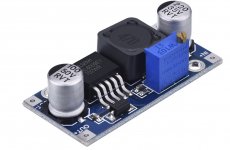
I guess you’re talking about these XL6009 modules? You have put an inductor in series with the output voltage into a capacitor to ground. Great idea to get rid of most of the high frequencies.
Is that all you added / modified? Did you notice any other spurious on the output (besides the 400 kHz)?
Regards, Gerrit
Is that all you added / modified? Did you notice any other spurious on the output (besides the 400 kHz)?
Regards, Gerrit
Attachments

Yup, that is the ebay module that has been around for a bit now.
The low level 400kHz ripple voltage from the module may be no issue at all (just an aesthetic one if seen on a scope waveform). I just aimed to see what practical parts could be used to attenuate the default level, given the ripple frequency and likely dc current that the module could be asked to output.
I had a reasonable go at trying to identify what seemed like some low level hash that could sometimes be seen on the output voltage waveform - often it was just associated with turn-on and then settled down to nothing. I disconnected the enable pin, and tried a few changes, including sitting pin 2 at a stable filtered rectified voltage, as well as redirecting the connection of pin 2 back to the input filter cap terminal along with direct pin 1 to 2 bypass cap. That hash appears to be related to when input voltage has a higher ripple level (rather than being fed by a heavily capacitor filtered feed). I also played around with different levels of input feed filter cap (and hence ripple voltage) to try and extend the diode conduction duty-cycle as much as possible, but the constant power load characteristic starts to noticeably affect the modules input current profile when feed voltage gets below about 3-4V, and there is a noticeable output voltage response disturbance as the feed voltage changes direction when the next diode current conduction starts up.
If the application is to dc heat only for one or two valves then the MT3608 would be my initial preference.
Last edited:
Oops, the MT3608 module actually showed a 1MHz ripple frequency, and I just checked that the cheap eBay module actually uses a TMI ST3508 device (with marking S35x) which has a nominal 1MHz switching frequency, but otherwise appears to have equivalent specs to the Aerosemi MT3608 device.
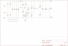
It is possible to do this Linear as well, if you use skottkey rectification you will get about 7VDC under the ripple, this is too low to use the most common LDO regulators like the LT1083 ECT, however if you use a pass device that has a very low VCEsat like the 2SC6144 you can use this schematic, provided you use it in the negative return lead.
All credit for the design goes to Mona, i forgot which topic this was discussed earlier.
If you want i can send you some PCB's for this schematic, the PCB's are scheduled to arrive next week.
All credit for the design goes to Mona, i forgot which topic this was discussed earlier.
If you want i can send you some PCB's for this schematic, the PCB's are scheduled to arrive next week.
Attachments
Hi V4lve lover,
I’m sure this will be fine for a regulator, but what about getting a higher output voltage than the input voltage. For example with a XL6009 I can use a 5.5 Volt input to get 6.3 Volt output. That is my only reason to use this step-up converter.
Regards, Gerrit
I’m sure this will be fine for a regulator, but what about getting a higher output voltage than the input voltage. For example with a XL6009 I can use a 5.5 Volt input to get 6.3 Volt output. That is my only reason to use this step-up converter.
Regards, Gerrit
Just a quick update. I have the XL6009 regulators now in place. I use one for each channel, where each channel has 2 6SN7 tubes, drawing approx. 1.2A @ 6.3VDC. I feed the regulators with a schottky bridge connected to the 6.3VAC winding. I use 66000 uF (3 x 22000 uF) capacitors with the bridge rectifier. The 6.3VAC winding is elevated to 40VDC.
I use shielded wiring now from the DC regulators to the 6SN7 tubes.
At the output of my KT150 PP I measure between 0,35 and 0,5 mV noise/hum accross my dummy load. This is inaudible with a speaker connected instead of the dummy load.
PS: I toasted two regulators by accident by reversing the + and - on the input side. I’m afraid they don’t like this very much and start smelling...
Regards, Gerrit
- Home
- Amplifiers
- Tubes / Valves
- DC heater challenge