I happened to buy one of these to evaluate on an EL84 SEP amp (1.8A for heater requirement).
The design looks mostly like I'd expect, but I was wondering if you had any insight on the use of the 15KuF on the output of the regulator ? The datasheet spec's 10uF, while the Tubelab SE-II has 4700uF on the output.
I'd say 15mF is unnecessary for sure. I use only 22uF for a 6SN7 running from a 7806 and there's no noise there. 15mF makes sense for a normal bridge/cap filter though.
^^^^^^^^ THISWhy?
6.3VAC with a quad of Schottky diodes (e.g. SB520/30/40) will give you almost 8VDC (probably even more, considering you're using just a fraction of winding's nominal current, so the AC voltage should be higher than 6.3V). That's even enough for some CRC filtering.
Forget winding stressing wasteful doublers, just do it right the first time.
IF it doesn´t work, THEN your transformer winding can´t take it. Period.
TONS of times I have rectified 6.3V AC with a regular silicon diode bridge and got >6.3V DC , so low drop schottkys should be even better.
Last edited:
What I do.
Good solution. Less dissipation. I would use CLC and/or 16V filter caps though.
Last edited:
DC Filaments:
I have used brute force Schottky bridge and CRC.
The R is adjusted to give 6.3VDC, according to the filament amps.
The advantage (*) of the R, is that is causes a slow start to the filaments.
Filament resistances are very low when cold, and increase as the filament warms up.
You may, or may not, consider the soft start to the filament as an advantage (*).
depends on the tubes, and how quick the B+ comes up.
AC filaments:
Here is a soft start Direct Heated Rectifier circuit.
Use a separate 6.3V filament winding (rectifier filaments and 12AX7 filaments do not work well together on the same 6.3V winding).
Connect a 0.65 Ohm resistor in series with a 2.0 Amp 5Y3 filament. The filament resistance is very low when cold, increases when hot.
That adds soft start to the B+.
Adapt the Resistor to match your favorite Direct Heated Rectifier, 2.0A, 3.0A, etc.
Last edited:
i suppress the urge to use regulators in dc filaments, ac worked just as fine,
i have done 4 6sn7 aikido using ac heating, but i also used merlinb's dc lifting technics...
you can make very quiet amps even with dc heating, and that to me is more challenging...
but having used smps bricks, i will used them on filaments for 300b and etc, i have seen it done, someone already posted this here before...
indeed, life is full of contradictions.... 😀
but i am not a one track mind, i will never hesitate to use whatever is available to me...
and that is because when it comes to electronics, i am agnostic.....
merely sharing what i have been thru...
but i am not a one track mind, i will never hesitate to use whatever is available to me...
and that is because when it comes to electronics, i am agnostic.....
merely sharing what i have been thru...
I was going to start my own thread but I'm facing a very similar "challenge" so thought it may be better to post here.
I am working on a single-ended EL84/12AT7 desktop headphone/speaker amp. My HD650 are 102db sensitive and in my past attempt at a tube HP amp hum was an issue.
Also, my mains fluctuates between 118-123 AC and I don't want to over/under voltage the heaters on my NOS tubes.
This is the primary reason I want to try regulated DC. (B+ is also regulated with Maida regulator)
SMPS block is an option, but also the circuit MelB proposed, which is similar to what is used in the Tubelab SE-II and in the eBay PCB from post #7.
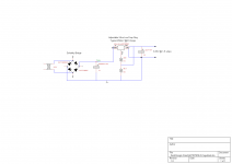
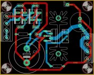
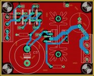
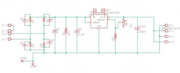
I want to make a PCB for a similar circuit with minor adjustments and smaller footprint, the draft schematic and board are attached.
Board dimensions are 2.6" x 2.1"
This would be used for 5 VDC or 6.3 VDC from a 6.3VAC tap, or you can wire dual secondaries in series for 12VDC.
For this PCB, potential BOM:
- SBLF10L25-E3/45 or similar Schottky rectifier w/ snubber caps
- Main filter cap is 16V 25d snap-in. (up to 33mF)
- Output cap up 16V 13d (22uF-5600uF)
- MIC29502WT regulator
- R1 is the bleeder resistor
Questions:
1) Any suggestions for snubber cap value? I've seen 220pF up to 0.1uF
2) Unsure about the output cap, George provided a pretty comprehensive response to the use of 4700uF in the TSE-II. https://www.diyaudio.com/forums/tubelab/331038-14-run-tse-die-92.html#post6446122
3) Where do you typically ground this DC circuit? Is there any advantage to elevating such as with AC, directly to ground or floating?
Any other comments or recommendations? Thanks!!
I am working on a single-ended EL84/12AT7 desktop headphone/speaker amp. My HD650 are 102db sensitive and in my past attempt at a tube HP amp hum was an issue.
Also, my mains fluctuates between 118-123 AC and I don't want to over/under voltage the heaters on my NOS tubes.
This is the primary reason I want to try regulated DC. (B+ is also regulated with Maida regulator)
SMPS block is an option, but also the circuit MelB proposed, which is similar to what is used in the Tubelab SE-II and in the eBay PCB from post #7.
I want to make a PCB for a similar circuit with minor adjustments and smaller footprint, the draft schematic and board are attached.
Board dimensions are 2.6" x 2.1"
This would be used for 5 VDC or 6.3 VDC from a 6.3VAC tap, or you can wire dual secondaries in series for 12VDC.
For this PCB, potential BOM:
- SBLF10L25-E3/45 or similar Schottky rectifier w/ snubber caps
- Main filter cap is 16V 25d snap-in. (up to 33mF)
- Output cap up 16V 13d (22uF-5600uF)
- MIC29502WT regulator
- R1 is the bleeder resistor
Questions:
1) Any suggestions for snubber cap value? I've seen 220pF up to 0.1uF
2) Unsure about the output cap, George provided a pretty comprehensive response to the use of 4700uF in the TSE-II. https://www.diyaudio.com/forums/tubelab/331038-14-run-tse-die-92.html#post6446122
3) Where do you typically ground this DC circuit? Is there any advantage to elevating such as with AC, directly to ground or floating?
Any other comments or recommendations? Thanks!!
Attachments
FWIW this is what a Pro manufacturer, 57 years experience, who makes thousands of amplifiers each month, to feed insane gain preamp filaments, gain which surpasses by orders of magnitude anything the wildest Hi Fi preamp may ever use:
* 6.3VAC winding (which also feeds all other tubes, including power ones):
* 1 bridge rectifier
* 4 x 3300uF caps
Period, nothing else, not even a humble 1 ohm resistor.
"Maybe" they know something about it. 🙄
* 6.3VAC winding (which also feeds all other tubes, including power ones):
* 1 bridge rectifier
* 4 x 3300uF caps
Period, nothing else, not even a humble 1 ohm resistor.
"Maybe" they know something about it. 🙄
Attachments
That says absolutely nothing. There is not a single person knowing all/there is progress/there is money to be made and possibly with at least costs as possible. The fact that they use DC is already a revolution 🙂
Please note that many tube circuits require elevated GND of the filament PSU!
3) Where do you typically ground this DC circuit? Is there any advantage to elevating such as with AC, directly to ground or floating?
Please note that many tube circuits require elevated GND of the filament PSU!
Last edited:

As a hum inducing factor, probably way less than that, since filamens get out of phase ripple applied to ends.
Whatever little ripple remains.
Whatever little ripple remains.
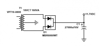
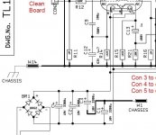
Creating a 'center tap' like this, I was surprised by the size of C3 & C1. If Marshall could have used a smaller cap for this purpose, they probably would have.
Your rectifier diodes should be rated 50V/10A. (10A01 part nr) higher voltage has more voltage drop
The repetitive peak current through the diodes is about 7 times higher than the output current, between 16 and 20A
Now look on the datasheet the instantaneous forward voltage vs current
the 10A diodes have about 1-1.5V at 17A loss: -3V
The transformer has maybe 200mOhm internal resistance, which is already compensated for 10A by design, but we take 5A peak more loss: -1V
we have 8.9V peak -4V= 4.9V
so it should not work
Schottkys have higher loss at high currents
Last edited:
Please note that many tube circuits require elevated GND of the filament PSU!
Is this true also for regulated DC?
From "Building Valve amplifiers":
The output of a DC heater regulator has virtually no AC present, so the LT 0V can be connected directly to the HT 0 V.
That aside, any recommendations before I send this board out?
I was going to start my own thread but I'm facing a very similar "challenge" so thought it may be better to post here.
I am working on a single-ended EL84/12AT7 desktop headphone/speaker amp. My HD650 are 102db sensitive and in my past attempt at a tube HP amp hum was an issue.
Also, my mains fluctuates between 118-123 AC and I don't want to over/under voltage the heaters on my NOS tubes.
This is the primary reason I want to try regulated DC. (B+ is also regulated with Maida regulator)
SMPS block is an option, but also the circuit MelB proposed, which is similar to what is used in the Tubelab SE-II and in the eBay PCB from post #7.
I want to make a PCB for a similar circuit with minor adjustments and smaller footprint, the draft schematic and board are attached.
Board dimensions are 2.6" x 2.1"
This would be used for 5 VDC or 6.3 VDC from a 6.3VAC tap, or you can wire dual secondaries in series for 12VDC.
For this PCB, potential BOM:
- SBLF10L25-E3/45 or similar Schottky rectifier w/ snubber caps
- Main filter cap is 16V 25d snap-in. (up to 33mF)
- Output cap up 16V 13d (22uF-5600uF)
- MIC29502WT regulator
- R1 is the bleeder resistor
Questions:
1) Any suggestions for snubber cap value? I've seen 220pF up to 0.1uF
2) Unsure about the output cap, George provided a pretty comprehensive response to the use of 4700uF in the TSE-II. https://www.diyaudio.com/forums/tubelab/331038-14-run-tse-die-92.html#post6446122
3) Where do you typically ground this DC circuit? Is there any advantage to elevating such as with AC, directly to ground or floating?
Any other comments or recommendations? Thanks!!
Yes it is true for regulated DC. It has to do with the maximum heater to cathode voltage that must not be exceeded. I know it from when the SRPP craze began. You could include the 2 resistors on the board just in case so the board can be used in such situations. As you are using it for filaments you can omit the 600 Ohm as there will be load in any case. For this regulator I would follow datasheet recommendations instead of looking at other schematics. It will work fine with 100 µF. Using extreme values like in the link has no real advantage. The writer uses many words but there is clearly stated that it worked OK from 22 µF upwards. Please note that you will be using it with EL84/ECC83 indirectly heated tubes.
* Please note that pin 1 and 2 of the potentiometer must be connected! I leave it to you to explain why. Pads for a resistor in parallel would not be a bad choice either.
* The heatsink should be larger and it should be farther away from the capacitors.
If you refer to the schematic of itsikhefez then you exaggerate. The circuit will perform OK with 6.3V (but not with 5V AC).
* Please note that pin 1 and 2 of the potentiometer must be connected! I leave it to you to explain why. Pads for a resistor in parallel would not be a bad choice either.
* The heatsink should be larger and it should be farther away from the capacitors.
Your rectifier diodes should be rated 50V/10A. (10A01 part nr) higher voltage has more voltage drop
The repetitive peak current through the diodes is about 7 times higher than the output current, between 16 and 20A
Now look on the datasheet the instantaneous forward voltage vs current
the 10A diodes have about 1-1.5V at 17A loss: -3V
The transformer has maybe 200mOhm internal resistance, which is already compensated for 10A by design, but we take 5A peak more loss: -1V
we have 8.9V peak -4V= 4.9V
so it should not work
Schottkys have higher loss at high currents
If you refer to the schematic of itsikhefez then you exaggerate. The circuit will perform OK with 6.3V (but not with 5V AC).
Last edited by a moderator:
Gerrit, is there a reason to use a DC heater supply for 6SN7's?
Have you confirmed that a DCV elevated AC heater with tuned humdinger and good layout is still too 'hummy' for your application, and was that due in any way to the proximity of the heater supply transformer?
You may also want to do a temporary test that uses a battery to power the heaters, but also operates the heater transformer in to an example rectifier/filter dc feed that is just powering a load resistor. The aim of such a test is to confirm the transformer and brute-force rectified heater winding does not pollute your low level signal electronics due to parasitic coupling of the rectification glitches and AC fields.
There is another way to generate a DC heater voltage. It rectifies the heater winding but has minimal filter capacitance to provide an intermediate DC + AC voltage waveform. A dc/dc is then used to boost that to a regulated higher DC voltage such as 12.6V. The aim is not to brute-force rectify the heater winding. A couple of small XL6009 or MT3608 pcb assemblies may do the job well - although not for the faint of heart. I haven't tried this setup yet, but just added it to my xmas wishlist of things to do.
Last edited:
Hi Tom,
I just ordered two Step-up Boost Converters XL6009 4A for testing. I will make the test with the battery again tomorrow (now charging).
So far the AC supply for the 6SN7’s seems to work quite well, but I still get hum somewhere. Heaters are elevated (around 40 VDC), humdinger is in place with a 10 uF film capacitor from the center tap to ground. I get 2 mV at the speaker output and need to get below 1 mV.
Regards, Gerrit
- Home
- Amplifiers
- Tubes / Valves
- DC heater challenge