Hi Andrew
Well undestood.
Your idea is ok to get the diode barrier potential of about 1.2V while mine is ok to get of about 0.6V. This means that mine is not wrong at all.
I don't understand why you are mentioning about VA values of the caps. I understand that the charge flow inside cap and its terminal potential have a fixed ratio. The point should be whether the cap is big enough for the needed current flow.
And, the two plates of the cap should be always open when it works. If the cap goes wrong, it would bacome short between the two plates. If the cap is getting old after repeated reverse bias (very low, though), the oxide of the anode might be dissolved and give the short between the two plates. If I use big capacitance and voltage rating, its life could be much longer.
After all, they are series in a line. Don't you think so?
Regards
jh
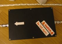
PS. The label makes you feel better . . . ?
Well undestood.
Your idea is ok to get the diode barrier potential of about 1.2V while mine is ok to get of about 0.6V. This means that mine is not wrong at all.
I don't understand why you are mentioning about VA values of the caps. I understand that the charge flow inside cap and its terminal potential have a fixed ratio. The point should be whether the cap is big enough for the needed current flow.
And, the two plates of the cap should be always open when it works. If the cap goes wrong, it would bacome short between the two plates. If the cap is getting old after repeated reverse bias (very low, though), the oxide of the anode might be dissolved and give the short between the two plates. If I use big capacitance and voltage rating, its life could be much longer.
After all, they are series in a line. Don't you think so?
Regards
jh
PS. The label makes you feel better . . . ?
Attachments
Hey JH,
If you are in a posistion to reduce your capacitance somewhat, you could end your reverse voltage issues by wiring the caps as BIPOLAR.
Use two caps in series to replace one; wire them + to +, or - to -. This is how bi/non polar caps are made.
Do you worry about the reverse voltage? I have had big caps explode... no good. But this was always at high (er) voltages.
Hi poobah
Mine is back2back.
The + terminal goes to the primary side of transformers (not visible) and through the transformer return back to + terminal of the other side of the cap.
Yeah, I experienced two explosions too.
It was due to reverse bias with high reverse voltage.
It made the inside liquid boil and increased the inner pressure
at high speed, and BANG!!!!!!!!!!!!!!!
Regards
jh
I see now,
You Do have back-kcab... just a round-a-bout way. Does this circuit fix your hum problem well?
You Do have back-kcab... just a round-a-bout way. Does this circuit fix your hum problem well?
Hi,
the diodes do NOT conduct on normal operating load.
The diodes only conduct when the peak voltage across the caps increases above the diode voltage.
The caps should be sized to keep the peak voltage (Vpk) due to AC current below your set limit (Vpk<0.6V or Vpk< 1.2V). Some of this AC capacity is used up when DC is actually present. i.e. Vpk + DCv < diode block voltage
The diodes will conduct when the DC blocker experiences an overload i.e. during start up or when excessive DC is present. In my opinion 0.6V of DC blocking ability is too low, I would go to at least two diodes and possibly three series diodes (1.2V to 1.8V).
In conclusion, when the DC blocker is working properly the peak voltage across the blocker is below the diode voltage limit and the impedance of the caps at line frequency determines the maximum load you can put through your blocker.
Finally, a Capacitor smoothing system after the main transformer rectifier has very high peak currents that are mirrored in the AC current flow into the transformer. This also uses up peak voltage capacity. Even more reason to go higher than two diodes.
Hi,
as pointed out earlier the back to back caps are split between the lines, one // pair on the live line and one // pair on the neutral line.
On safety alone this is not recommended.
I believe it would be safer to put the whole DC blocker on the neutral line. Others would adopt the industry standard and NEVER put the DC blocker in the neutral line.
What label - the safety warning inside the lid? to help protect future repair technicians.
I think this is a bit brittish because no place else they keep order of the live and the neutral line. I think the rest of the world you just plug in the socket regardless of polarity. I can't see what inserting a DC filter into the neutral line what kind of harm it would cause. Can somebody enlighten me please?
Glad to.
Picture a primary connected to one of two DC filters. One having the filter in the hot line, the other in the neutral. Now picture the DC filter letting the smoke out and becomming open circuit.
In the case where you have the filter in the hot line, your primary is now disconnected and all is well.
In the case where you have the filter in the neutral line, your primary stays live, all is dangerous.
You can then see that standard isolation precautions are suitable in either case, yet one remains potentially far more deadly in case of fault. That's my understanding of this tired debate anyway (it's come up in other threads).
Regards,
Chris
Hi all,
Chris is right. When the DC blocker fails opencircuit, it is much safer to have the opencircuit in the hot (live) line. Then all down stream is dead. The Technician lives on to work another day.
However, this is where I disagree, when the unit is working correctly the DC blocker (including all it's wiring and casings) is working at line voltage and is potentially very dangerous if unsuspecting fingers are poking around or metal tools get dropped.
In an operational unit when set up or testing is in progress I believe that the DC blocker would be safer in the neutral line. This is completely in contravention of standard UK practice but it has a safety advantage. A safety label on or in the box is mandatory and possibly a LED alarm showing a volts drop across the blocker indicating that all is not dead.
Jh6,
which bit do I not understand?
Hi,
I don't think I can agree with that. Such a circuit can simply not have easy access/quick disconnects or anything.
Even though this is a DIY thing, technicians are trained and know what not to do, and if they don't, no amount of shinny red labels will save them anyway. It also seems unlikly the OP would be sending this off to a technician for repair considering he built it himself.
So we can forget about the technician I think.
What the concern is are all the unknown that it's plugged into, all the different ways everything can go wrong in one big chaotic cascade... smoke and fire.
Seems to make alot more sense to put it in the hot line when you think about it like that?
Regards,
Chris
poobah said:Does this circuit fix your hum problem well?
Yes, it works well for reduced transformer buzz and for audio and video quality. I¡¯m sure that the ac supply in my place must be polluted one.
By the way, I think that the dc-blocked-using-diode sine wave is no more real sine wave because of the disturbance at the zero crossing point. This would create high order harmonics, and if it arrives at certain level, it could make the transformer back to cry. Therefore, blocking dc more than 0.6-1.2V is considered not a good idea.
As I already informed, I made 0.6V dc blocker outside my pre and power amps and in addition another 0.6V dc blocker inside each of them. So, they work together to block dc of total about 1.2V.
Regards
jh
In general, the neutral should be as close to ground as possible; many hidden capacitors appear when neutral is allowed to shift.
But for safety, please, relax, every time we make the world safer for idiots... we all suffer. The circuit design is not crazy. I would put the whole circuit on the HOT and NOT the NEUTRAL... I live in the U.S. But some countries are smarter (or newer) than the U.S. ... they have NO hot and neutral in the first place.
Why??? because the electrical person who wires, connects, the houses does not care... U.S., BFE, Mars, Asia, Moon, etc...
Hi all,
I have the same problem of vibrations with my transformers and i'm pretty sur that it comes from bad power line 'cause i tried with differents big transformers (300VA) and I heard the same noise through them.
Here is 2 designs i found in the forum:
http://www.diyaudio.com/forums/attachment.php?s=&postid=780350&stamp=1133492948
http://www.diyaudio.com/forums/attachment.php?s=&postid=778609&stamp=1133302016
So, i'm wondering which one of them is the most effective ?
Can or should i use both ?
Does it exist others ?
Thanks in advance.
Emeric.
Hi,
neither, they both have a problem.
What is the size of your load?
Scale the caps to pass the AC current into the load with a peak voltage less than the diode drop. I would eliminate the connection between the junction of the caps to the junction of the diodes.
The diodes are there to bypass the caps at switch on (a once only large current surge) or when the mains fuse blows.
Either the neutral or the live goes straight through. Only one of these should have the DC block installed.
Use big power diodes, just in case you ever ask this to pass a high fault current.
Do not fit a resistor bypass.
You can use low voltage caps. I use 16V but I have seen 10V recommended.
Ok thanks,
my load is about 1400W
I don't understand what does that mean . 🙁
my load is about 1400W
Scale the caps to pass the AC current into the load with a peak voltage less than the diode drop. I would eliminate the connection between the junction of the caps to the junction of the diodes.
I don't understand what does that mean . 🙁
Hi,
search for DC filter. There are lot´s of schematics here that are the way Andrew pointed out.
Normally you only need one big cap and 4 to 6 diodes. The cap is in series with the live wire. 2 sets of Two (1.4V) or three (2.1V) diodes in series are parallel to the cap to avoid too much DC voltage over the cap.
http://www.diyaudio.com/forums/attachment.php?s=&postid=16083&stamp=1012084233
You can use just one cap and the antiparallel diodes, if your dc is higher that 0,7V ( wich it normally isn´t) you can use 4 diodes (2 in series) or even 6.
You could also read this:
http://www.diyaudio.com/forums/showthread.php?threadid=83784&highlight="DC+Filter"
William
Hi,
use F=1/2PiRC to find C.
If your continuous load is 1400W from 110Vac, then rms current I=P/V=12.7Aac. Peak current into a capacitor input filter is even higher, but for simplicity I'll ignore that crest factor.
If you decide to use cascaded diodes in antiparallel then Vpk across the caps is 1.4Vpk (two in series & four in total).
The equivalent R for 1.4Vpk and 18Apk (=1Vac & 12.7Arms) R=V/I=1.4/18=0r078
Substituting into that first formula C=1/2PiRF=1/[2*3.142*0.078*60]=0.034F=34mF (=34,000uF)
If you put caps in back to back the effective capacitance is halved so one needs 68mF+68mF back to back to meet a continuous load of 1400W on 110Vac and keep the bypass diodes (1.4Vpk) inactive at the peak of the current flow.
Is your load really 1400W continuous?
If the continuous load is 200W and peak load is 1kW then design for 200W and accept an infrequent bypass current thro' the diodes. You decide what infrequent is. If you go for 1n5402 diodes they will run hotter than a power bridge and thus should only pass less frequently I would not recomend 1n4002 but they may work if the caps are kept big enough and a soft start is used on your bigger loads.
BTW,
you can test the effectiveness of the DC blocker by monitoring the voltage across it after you have installed it. If the peak voltage is less than the diode voltage then the caps are big enough.
- Status
- Not open for further replies.
- Home
- Amplifiers
- Power Supplies
- dc-filtering-ac-power-station