Thanks Tony, that's a nice paper. I did have a (badly scanned) copy, This is much better. Actually anything out of the old Philips technical Library with the name Rodenhuis on is is worthwhile.Jan, this hum compilation article details references to the Vhk topic, including Klemperer, Kock, RCA, and Rodenhuis, and shows some more Rhk results.
PRR, thanks for that 1940 link. At that time the control of impurities in the heater coating was not well understood, and RCA appears to have done a lot of work to improve that (eg. the 1962 RCA Electron Tube Design book). Also at that time, hum was not as objectionable as it was in the 1950's to today, once hi-fi took off.
Time has also shown forum thread examples of valves exhibiting degraded Rhk causing noticeable hum - with the remedy being to replace the valve. Some of those examples also support Rhk degradation due to natural circuit Vhk dc bias (ie. cathodyne circuit), and the Rodenhuis reference has a section on heater-cathode shorts.
A year or two ago I got my hands on an extensive interview of a guy who had been chief of QA at Philips tube manufacturing. I then found out that these guy did not really have a strong theoretical base. On the polarity of the voltage between H and K you can find any opinion, pos, neg and zero. So it probably is not something to greatly worry about.
I won't continue to split hairs, but I was triggered by the statement that elevating the heater decreases hum, and that is incorrect. There simply is no mechanism for that.
Edit: There's Robert Tomer's "Getting the most out of vacuum tubes", which I used for my AudioXpress article.
Then Morgan Jones pointed me to "Materials and Processes of Electron devices" by Max Knoll.
Jan
That is true for a dc powered heater, as is the topic for this thread. But is not true for AC powered heaters where a residual hum current passes through Rhk.I won't continue to split hairs, but I was triggered by the statement that elevating the heater decreases hum, and that is incorrect. There simply is no mechanism for that.
I don't know what you mean by residual hum current through Rk, seems to me a design issue. At any rate, how would putting that heater at say 100VDC change that? Maybe you can add a scribble, I have a hard time visualizing it.That is true for a dc powered heater, as is the topic for this thread. But is not true for AC powered heaters where a residual hum current passes through Rhk.
Jan
The argument goes that current can only flow from negative to positive, so a heater voltage more positive than cathode minimizes leakage current. Ancient stuff, hence Best Practice, but "cliches are often true". Imagine a large value, diodic, poor quality resistor between heater and cathode - that's the potential issue.
All good fortune,
Chris
All good fortune,
Chris
Really. Wow. I think you just denied that AC can exist.
So if we increase the DC across that "large value, diodic, poor quality resistor between heater and cathode" the ac current will be lower?
Jan
* Yes clichés are often true. OTOH, I am often encouraged by a quote from Bertrand Russell: "The fact that an opinion has been widely held is no evidence whatever that it is not utterly absurd; indeed in view of the silliness of the majority of mankind, a widespread belief is more likely to be foolish than sensible."
YMMV
Jan
I'm sorry if I've inadvertently offended you. That was certainly not my intention. Please forgive me if that were the case.
And yes, the classic argument is that leakage current will be lower between a more positive element and a less positive one, even at similar temperatures, than the other way round. Kinda like a (poor quality) thermionic diode.
All good fortune,
Chris
And yes, the classic argument is that leakage current will be lower between a more positive element and a less positive one, even at similar temperatures, than the other way round. Kinda like a (poor quality) thermionic diode.
All good fortune,
Chris
No no, Chris, no offending assumed or felt!
In all leakage cases, I invariantly found that the larger the voltage across an element (any element or part) the larger the leakage.
This is what physics as well as practical cases tell us.
So that will be my position until shown otherwise.
Jan
In all leakage cases, I invariantly found that the larger the voltage across an element (any element or part) the larger the leakage.
This is what physics as well as practical cases tell us.
So that will be my position until shown otherwise.
Jan
A good case could be made that the difference in temperature between heater and cathode is too small to make its diodic character significant for leakage. There will always be some temperature difference, and always in the direction of hotter heater and (relatively) cooler cathode, but space charge between them - who knows?
The classical argument depends on some diodic preference of leakage current flow, and a modest (25VDC is the classic recommendation) bias to discourage stragglers. It may be right or it may be wrong, but it sure gonna get me when I'm gone.
Always the best,
Chris
The classical argument depends on some diodic preference of leakage current flow, and a modest (25VDC is the classic recommendation) bias to discourage stragglers. It may be right or it may be wrong, but it sure gonna get me when I'm gone.
Always the best,
Chris
After some searching, let me quote from own work 😎 :
"DC heater power in itself is detrimental to tube life. At switch-on, the large inrush currents and the mechanical spiral construction of the heater always cause a very small mechanical movement of the heater structure inside the cathode. With a DC supply, these movements are always in the same direction and of similar magnitude, causing a kind of scraping. Over many switch-on cycles, this scraping can lead to weakening of the isolation between the heater and the cathode, causing crackling sounds and eventually failure. So unless you have an issue with hum, AC powering the heater is better for tube life."
https://audioxpress.com/article/the-internal-life-of-vacuum-tubes
Bill Reeves wrote about it too, see:
https://audioxpress.com/article/con...end-the-life-of-your-amplifier-s-vacuum-tubes .
Enjoy!
Jan
With all due respect, I need second opinions. Especially for living authors without megabuck test budgets.
"I invariantly found that the larger the voltage across an element (any element or part) the larger the leakage."
Not simple "leakage", more "emission". And you know emission saturates, especally on metal emitters (less so for RE oxides).
Valve Hum, C.E. Cooper, Electronic Engineering, July 1944
https://worldradiohistory.com/UK/Electronic-Engineering/40s/Electronic-Engineering-1944-07.pdf


Sylvania Electron Tube Application Notes, 1960?
https://frank.pocnet.net/other/Sylvania/Sylvania_ElectronTubeApplicationNotes_1960.pdf

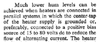
"A reduction in hum may be realized if the heater transformer can be grounded at the center tap. In the case of a heater transformer that has one side grounded, the side above ground will swing (assuming 2 V bias) from —10.9 to +6.9 volts with respect to cathode. With the center tap grounded, the voltage excursions between cathode and heater are only from —6.5 to +2.5 volts. The 180° phase difference in the currents in the two halves of the heater further reduces hum with the latter arrangement due to cancellation. Figure 3 shows that saturation frequently occurs above a certain value of heater-cathode potential. If it is possible to operate the tube with a DC bias of approximately 30 volts between the heater and cathode, advantage can be taken of this effect as a means of reducing hum. The bias can be applied in either direction as shown by Figure 3, curve A. Variations in AC potential about the operating point will not introduce a corresponding current change, since the current is saturated throughout this region."
Dalmura, Hum Article (scrapbook of old data/tips)
https://dalmura.com.au/static/Hum article.pdf

Controlling hum in audio amplifiers. L. Fleming, Radio & Television News, Nov 1950.
https://worldradiohistory.com/Archive-Radio-News/50s/Radio-News-1950-11-R.pdf
Heater Cathode Insulation Performance, Klemperer, Westinghouse, 1936
https://dalmura.com.au/static/Heater cathode insulation performance.pdf
EICO HF52 blurb-page

"I invariantly found that the larger the voltage across an element (any element or part) the larger the leakage."
Not simple "leakage", more "emission". And you know emission saturates, especally on metal emitters (less so for RE oxides).
Valve Hum, C.E. Cooper, Electronic Engineering, July 1944
https://worldradiohistory.com/UK/Electronic-Engineering/40s/Electronic-Engineering-1944-07.pdf
Sylvania Electron Tube Application Notes, 1960?
https://frank.pocnet.net/other/Sylvania/Sylvania_ElectronTubeApplicationNotes_1960.pdf
"A reduction in hum may be realized if the heater transformer can be grounded at the center tap. In the case of a heater transformer that has one side grounded, the side above ground will swing (assuming 2 V bias) from —10.9 to +6.9 volts with respect to cathode. With the center tap grounded, the voltage excursions between cathode and heater are only from —6.5 to +2.5 volts. The 180° phase difference in the currents in the two halves of the heater further reduces hum with the latter arrangement due to cancellation. Figure 3 shows that saturation frequently occurs above a certain value of heater-cathode potential. If it is possible to operate the tube with a DC bias of approximately 30 volts between the heater and cathode, advantage can be taken of this effect as a means of reducing hum. The bias can be applied in either direction as shown by Figure 3, curve A. Variations in AC potential about the operating point will not introduce a corresponding current change, since the current is saturated throughout this region."
Dalmura, Hum Article (scrapbook of old data/tips)
https://dalmura.com.au/static/Hum article.pdf
Controlling hum in audio amplifiers. L. Fleming, Radio & Television News, Nov 1950.
https://worldradiohistory.com/Archive-Radio-News/50s/Radio-News-1950-11-R.pdf
Heater Cathode Insulation Performance, Klemperer, Westinghouse, 1936
https://dalmura.com.au/static/Heater cathode insulation performance.pdf
EICO HF52 blurb-page
Well you guys certainly know how to put me to work ;-)
All interesting papers, and I will file them for future reference. But what I was looking for, some reason to elevate the heater above cathode with a DC voltage to reduce hum, backed up by some reasoning why that would work, I didn't find it.
The only reference to it was the attached, but again it was offered without any backing. So either this is one of those things we forgot, like how to build a pyramid. Or it is one of those wrong ideas that have started in the past and are repeated without any proof, like the idea that low open loop bandwidth in an opamp causes TIM.
Jan
Attachments
Jan, the mechanism is a parasitic effect of heater AC voltage leaking in to the cathode current circuit as an extra current that would be observable with a spectrum analyser. The lower the value of Rhk and the higher the value of Chk, the higher the hum current in the cathode circuit.
If the cathode circuit was a simple input gain stage with cathode bias, and the cathode resistor was not bypassed by a large capacitor, then their is a hum voltage generated at Vk, which becomes part of the amplified input signal. Rhk can vary a lot between sample tubes, so not a concern for most. Also many first stages bypass their cathode resistor, so again not a concern. And it was one reason why many early tape decks used grounded cathode circuits.
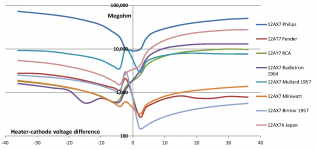
As PRR pointed to in post #51, the incremental Rhk as a function of Vhk increases as Vhk moves away from around zero. Attached is a batch of Rhk plots I did for the vintage 12AX7 I had to hand - the test method used DC levels as in attached setup. Only high gain low-level input stages may benefit from very high resistance. Note that Ckh capacitance is likely dominating hum leakage current for typical 12AX7 Rhk resistance levels at mains fundamental frequency, and would be a worse contributor for other higher frequency heater voltage hash (from the mains voltage itself, and from B+ rectifier spikes coupling back through the PT windings.
Note that Rkh resistance varies with applied voltage and can vary by an order of magnitude depending on the applied voltage (ie. test method dependant), and can be symmetric or asymmetric around zero, but is typically at its lowest level near 0V. Samples can vary in resistance over orders of magnitude.
For large valve applications, Rhk resistance is almost a negligible parameter, especially for fixed bias amps. This would also apply to grid-leak biased low level stages - which may have been seen as a benefit in days of old.
A degrading level of Rhk resistance may indicate a degrading valve, which could lead to a short (eg. whisker growth) and hence lead to other annoying effects (eg. pops).
If the cathode circuit was a simple input gain stage with cathode bias, and the cathode resistor was not bypassed by a large capacitor, then their is a hum voltage generated at Vk, which becomes part of the amplified input signal. Rhk can vary a lot between sample tubes, so not a concern for most. Also many first stages bypass their cathode resistor, so again not a concern. And it was one reason why many early tape decks used grounded cathode circuits.
As PRR pointed to in post #51, the incremental Rhk as a function of Vhk increases as Vhk moves away from around zero. Attached is a batch of Rhk plots I did for the vintage 12AX7 I had to hand - the test method used DC levels as in attached setup. Only high gain low-level input stages may benefit from very high resistance. Note that Ckh capacitance is likely dominating hum leakage current for typical 12AX7 Rhk resistance levels at mains fundamental frequency, and would be a worse contributor for other higher frequency heater voltage hash (from the mains voltage itself, and from B+ rectifier spikes coupling back through the PT windings.
Note that Rkh resistance varies with applied voltage and can vary by an order of magnitude depending on the applied voltage (ie. test method dependant), and can be symmetric or asymmetric around zero, but is typically at its lowest level near 0V. Samples can vary in resistance over orders of magnitude.
For large valve applications, Rhk resistance is almost a negligible parameter, especially for fixed bias amps. This would also apply to grid-leak biased low level stages - which may have been seen as a benefit in days of old.
A degrading level of Rhk resistance may indicate a degrading valve, which could lead to a short (eg. whisker growth) and hence lead to other annoying effects (eg. pops).
Attachments
Ahhh finally, that does make sense! Now I can understand where the preference for 30VDC Vhk comes from!
Thanks for the education. In your measurement did you by chance also measured the actual Ikh current as a function of the bias, that would complete the story.
Jan
Thanks for the education. In your measurement did you by chance also measured the actual Ikh current as a function of the bias, that would complete the story.
Jan
It seems his Rhk measurements are derived from Ihk measurements (Volts across a 1M Ohm resistor). Much thanks for this data, and like all real answers, it raises new questions! It looks much less asymmetrical than classic models would have predicted, or is that all from the log scale?
Excellent work, Ladies and Germans (Groucho Marx reference kids)
Chris
Excellent work, Ladies and Germans (Groucho Marx reference kids)
Chris
Yes, great work! And, as you say, it raises new questions.
For instance, there seem to be some regions where Rhk exhibits a neg resistance behavior.
I learned long ago that whenever Mr. negative resistance is around, Mr. cancellation is normally not far away. 😎
Jan
For instance, there seem to be some regions where Rhk exhibits a neg resistance behavior.
I learned long ago that whenever Mr. negative resistance is around, Mr. cancellation is normally not far away. 😎
Jan
Walter - perhaps a link would help, as the on-line manuals don't appear to have 'Paragraph G'.
Chris, my comment would be that some examples show symmetric behaviour, and other examples show asymmetric behaviour (where either positive or negative elevation would provide a significantly higher Rhk). So making a comparison to any one model would be a bit like cherry picking, especially as the working history of all the example tubes is unknown.
Jan, the characteristic near 0V elevation is prone to measurement issues. My view at the time was that the variable response at 0V bias is partly due to measurement resolution and the decay/polarisation effect due to changing a static test condition, but may also be due to non-zero electron emission current at 0V [Electron tube design, RCA, 1962. pp.232]. In all examples, the value of Rhk increases as elevation magnitude increases away from zero.
I find the symmetry interesting because it seems, at first blush, to contradict the classic model, as PRR has given us. Maybe this is somehow related to aging. If I knew something about the space charge between heater and cathode, I'd be dangerous.
Again, much thanks,
Chris
Again, much thanks,
Chris
OK, that makes sense. I should not see something that isn't there.[]
Jan, the characteristic near 0V elevation is prone to measurement issues. My view at the time was that the variable response at 0V bias is partly due to measurement resolution and the decay/polarisation effect due to changing a static test condition, but may also be due to non-zero electron emission current at 0V [Electron tube design, RCA, 1962. pp.232]. In all examples, the value of Rhk increases as elevation magnitude increases away from zero.
Jan
- Home
- Amplifiers
- Tubes / Valves
- DC Elevation