Its only available in Dutch, unfortunately. Its a detailed analysis of SRPP, Asym-SRPP, mu-follower, beta-follower, the whole family.
I'm trying to get the publisher to re-publish in English, so far no luck.
It's a very valuable book.
Jan
I'm trying to get the publisher to re-publish in English, so far no luck.
It's a very valuable book.
Jan
Thanks for the info Jan. I found it on Amazon. Unfortunately out of stock and also only in Ditch. It would sell very well in English. Let me know if this happens because I would definitely buy one.Its only available in Dutch, unfortunately. Its a detailed analysis of SRPP, Asym-SRPP, mu-follower, beta-follower, the whole family.
I'm trying to get the publisher to re-publish in English, so far no luck.
It's a very valuable book.
Jan
Cheers
Ian
Yes, I should translate it in English. I have some experience with publishing from my Linear Audio years.
But it's a hell of a job and boring. I need to revv up my ambition 😕
Jan
But it's a hell of a job and boring. I need to revv up my ambition 😕
Jan

Just checking why you want to elevate the heater when the heater is being DC powered ? Elevation (either positive or negative) is normally done as a way to increase the effective resistance between heater and cathode, which suppresses the AC current being leaked into the cathode circuit by the AC heater voltage via that Rhk. DC powering the heater removes the AC voltage across Rhk, and also across Chk, and hence removes that hum leakage current path (that may or may not then cause some hum signal to couple in to the audio signal).I am planning on DC heating some driver tubes with the Pete Millett regulated DC boards. If I want to elevate the circuit, do I tie the virtual center tap I'd create to the voltage divider or is there another way of accomplishing the elevation? I am not sure how elevating the center tap would effect the DC boards.
As far as I know, elevating a heater is done to avoid exceeding the max Vhk. Like in a cascode or SRPP, if one K is around ground level and the other at half B+. If both heaters are fed from a grounded winding, the max Vkh from the top tube may be exceeded. By elevating the heater winding to say 1/4 B+. neither max Vkh is exceeded. AC or DC heater is irrelevant here.
I never heard about elevating a heater for the other reason, and I don't think it would work. Increasing Vkh always increases leakage.
Jan
I never heard about elevating a heater for the other reason, and I don't think it would work. Increasing Vkh always increases leakage.
Jan
I did see schematics of amplifiers in which the heater supply was elevated by connecting it to the cathodes of the power tubes which were operating with a shared cathode bias resistor.
On the site of The Valve Wizard it is described too: The Valve Wizard - Heater / Filament Supplies
On the site of The Valve Wizard it is described too: The Valve Wizard - Heater / Filament Supplies
Yes there are many ways to do it, it a basic engineering thing. The purpose is always to avoid exceeding the max Vkh to prevent a short or excessive leakage.
Jan
Jan
Hi Ian,Which book is that? I cannot find it mentioned in this thread.
Cheers
Ian
It's this book: https://www.bol.com/nl/nl/p/buizenversterkerschakelingen/1001004006847335/
It's in Dutch. I'm not sure if it's published in English somewhere.
Jan, elevation is quite a common technique for hum reduction, and is not exclusively used for Vhk limit issues, but yes I forgot to add in the Vhk limit issue as I missed WntrMute2 reference to using a follower stage.
The 6S4A has a 200Vpk Vhk rating, and the EF86 has a 100V rating, so the extreme elevation limit is no more than 100V (assuming EF86 cathode is close to gnd level), which then also constrains the 6S4A supply voltage to no more than 300Vdc plus something like 50V (depending on the 6S4A loadline and 0Vg plate curve). In general, its better not to operate Vhk continuously close to or at its limit (as that can cause long term reduction in Rhk), which tends to suggest keeping the elevation suitably below 100V (and the 6S4A supply lower as well), or alternatively doing some periodic maintenance on the EF86 (either measuring its Rhk, or swapping it out).
The 6S4A has a 200Vpk Vhk rating, and the EF86 has a 100V rating, so the extreme elevation limit is no more than 100V (assuming EF86 cathode is close to gnd level), which then also constrains the 6S4A supply voltage to no more than 300Vdc plus something like 50V (depending on the 6S4A loadline and 0Vg plate curve). In general, its better not to operate Vhk continuously close to or at its limit (as that can cause long term reduction in Rhk), which tends to suggest keeping the elevation suitably below 100V (and the 6S4A supply lower as well), or alternatively doing some periodic maintenance on the EF86 (either measuring its Rhk, or swapping it out).
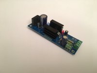
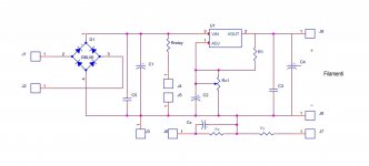
HiAre those boards something you have available commercialy? The form factor seems perfect.
I have some pcb to sell; are comes from some my project
It use LM350.
In this photo a double use around my LCR phono preamp; in the bottom right . One is elevated and other not.
Hum insertion into the K happens capacitively and/or inductively. None of that changes by elevating the H.Jan, elevation is quite a common technique for hum reduction, and is not exclusively used for Vhk limit issues, but yes I forgot to add in the Vhk limit issue as I missed WntrMute2 reference to using a follower stage.
The 6S4A has a 200Vpk Vhk rating, and the EF86 has a 100V rating, so the extreme elevation limit is no more than 100V (assuming EF86 cathode is close to gnd level), which then also constrains the 6S4A supply voltage to no more than 300Vdc plus something like 50V (depending on the 6S4A loadline and 0Vg plate curve). In general, its better not to operate Vhk continuously close to or at its limit (as that can cause long term reduction in Rhk), which tends to suggest keeping the elevation suitably below 100V (and the 6S4A supply lower as well), or alternatively doing some periodic maintenance on the EF86 (either measuring its Rhk, or swapping it out).
Jan
It is widely assumed that DC elevation may reduce electrolytic leakage in some samples.Hum insertion into the K happens capacitively and/or inductively. None of that changes by elevating the H.
7MB PDF of Electronics Magazine 1940, note from Tung-Sol
The capacitance between heater and cathode, being of the order of 10 μμf, is too small to constitute a leakage path.
When a transformer is used, hum will be reduced by grounding the center of the heater winding. Hum can be reduced to a negligible value by use of sufficient bias between heater and cathode to prevent the net voltage reversing. This condition occurs in infinite impedance detectors and certain cathode loaded circuits.
Hum, resulting from emission of charges from the heater to other electrodes, is reduced by decreasing heater temperature, by keeping the impedance of the electrode circuits low and by keeping the electrodes constantly biased with respect to the heater.
ELECTRONICS - February 1940
Sorry, I don't see any opportunity for 'electrolytic leakage' in your quote.
Grounding the heater winding mid point is done on the assumption that the outsides of the heater wire will swing equally and opposite with heater voltage, hoping for some cancellation. There may or may not be some value in that, I would have to look it up.
If you can't ground the heater winding center, you can add a small DC so that neither end of the heater reverses voltage, but what does that give you?
It has, at any rate, nothing to do with elevating heaters to avoid H-K breakdown or excessive leakage.
Jan
Jan, this hum compilation article details references to the Vhk topic, including Klemperer, Kock, RCA, and Rodenhuis, and shows some more Rhk results.
PRR, thanks for that 1940 link. At that time the control of impurities in the heater coating was not well understood, and RCA appears to have done a lot of work to improve that (eg. the 1962 RCA Electron Tube Design book). Also at that time, hum was not as objectionable as it was in the 1950's to today, once hi-fi took off.
Time has also shown forum thread examples of valves exhibiting degraded Rhk causing noticeable hum - with the remedy being to replace the valve. Some of those examples also support Rhk degradation due to natural circuit Vhk dc bias (ie. cathodyne circuit), and the Rodenhuis reference has a section on heater-cathode shorts.
I have not personally observed the effect of DC elevation on hum. I defer to the Dead Men and to historians like trobbins.
Here's another mention from 1962.

Here's another mention from 1962.
It's always been Best Practice to keep the heaters positive in respect to the cathode, if possible. Otherwise, the cathode starts to think that it's an anode, and the heater is its cathode. It very often doesn't much matter, but it's still considered Best Practice.
All good fortune,
Chris
All good fortune,
Chris
I think that 'best practice' is just a tale based on practicality, as it's easier to elevate the heater positive for a common cathode biased circuit, as typically found as the input stage of an amp/preamp (where hum generation is most sensitive). An alternate 'best practise' is that most cathodyne circuits would have the heater negative. Nowadays we have the ability to measure hum very easily at really low levels, and to tube swap to identify poor tubes, or alternatively to measure Rhk with modern digital megohmmeters at 100Vdc.
- Home
- Amplifiers
- Tubes / Valves
- DC Elevation