"Is there not a better alternative which goes from mains to HV DC."
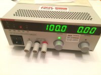
Sure. Xantrex XHR-600 $1000 (1st pic)
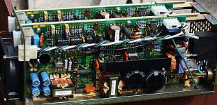
I did find some custom Xantrex Dual supplies (isolated Output 55V to 155V regulated, 300 Watt each channel) for $30 each on Ebay once. (2nd pic, cover removed)
But a much simpler approach can bring huge benefits.
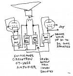
(3rd pic) No OT needed, flawless impedance conversion.
Just uses a set of standard LV supplies, and a set of simple square wave HF inverters. (555 oscillator into 2 Power Mosfets into a center tapped LV primary to HV secondary ferrite xfmr into a bridge rectifier, no capacitors, no regulation) The units on Ebay are not made correctly for this use unfortunately. This would be a very simple PC board to design for everyone. Just the custom wound ferrite xfmr is needed. Square wave switching is required (not a "boost" converter like on Ebay). One can even remove the VHF switching glitches by using two converters in parallel with the 555 timer switching phase shifted 90 degrees between them. (the minute discontinuity during the square wave rise/fall times get removed by the other converter being in full conduction at that time, reserved for ultra-purists who can "hear" above 10 Mhz)
Sure. Xantrex XHR-600 $1000 (1st pic)
I did find some custom Xantrex Dual supplies (isolated Output 55V to 155V regulated, 300 Watt each channel) for $30 each on Ebay once. (2nd pic, cover removed)
But a much simpler approach can bring huge benefits.
(3rd pic) No OT needed, flawless impedance conversion.
Just uses a set of standard LV supplies, and a set of simple square wave HF inverters. (555 oscillator into 2 Power Mosfets into a center tapped LV primary to HV secondary ferrite xfmr into a bridge rectifier, no capacitors, no regulation) The units on Ebay are not made correctly for this use unfortunately. This would be a very simple PC board to design for everyone. Just the custom wound ferrite xfmr is needed. Square wave switching is required (not a "boost" converter like on Ebay). One can even remove the VHF switching glitches by using two converters in parallel with the 555 timer switching phase shifted 90 degrees between them. (the minute discontinuity during the square wave rise/fall times get removed by the other converter being in full conduction at that time, reserved for ultra-purists who can "hear" above 10 Mhz)
Attachments
Last edited:
"Is there not a better alternative which goes from mains to HV DC."
Sure. Xantrex XHR-600 $1000 (1st pic)
I did find some custom Xantrex Dual supplies (isolated Output 55V to 155V regulated, 300 Watt each channel) for $30 each on Ebay once. (2nd pic, cover removed)
But a much simpler approach can bring huge benefits.
(3rd pic) No OT needed, flawless impedance conversion.
Just uses a set of standard LV supplies, and a set of simple square wave HF inverters. (555 oscillator into 2 Power Mosfets into a center tapped LV primary to HV secondary ferrite xfmr into a bridge rectifier, no capacitors, no regulation) The units on Ebay are not made correctly for this use unfortunately. This would be a very simple PC board to design for everyone. Just the custom wound ferrite xfmr is needed. (the turns ratio, squared, of the ferrite xfmr determines the OT impedance transformation)
Square wave switching is required (not a "boost" converter like on Ebay). One can even remove the VHF switching glitches by using two converters in parallel with the 555 timer switching phase shifted 90 degrees between them. (the minute discontinuity during the square wave rise/fall times get removed by the other converter being in full conduction at that time, reserved for ultra-purists who can "hear" above 10 Mhz)
Don,
I believe your diagram resembles David Berning's ZOTL patent, which may be expired by now. My attempts to build one of these back when the patent was new resulted in 20 or so exploded mosfets.
I first learned about this when I worked in a research group at Motorola. A coworker's patent was cited as a reference in Berning's ZOTL patent.
Berning also holds an expired patent on screen drive, and one on a hybrid cascade preamp.
Tube amplifiers for high-end audio by The David Berning Company
Returning to the subject; i find it a good solution to have B+ made in 2 steps :
first 12V DC , this can be used for filaments, then DC/DC to B+
12V can be obtained in varoius ways, a wallwart solves the legal problem of
EU-certification ( the device has no direct connection to mains) and the combination
would be more then enough to power a preamp or riaa device.
Powering a power amp is another issue, and here i guess one both have to
confirm to EU-certificate and also go straight from 220AC to DC /DC . Just like
any of the switching powersupplies available for low voltages just adopted to
supply 400+ Volts.
I might be wrong about the need for certification, please correct me on this matter
( i live within EU and has no plans to exports outside)
But again, i am interested in the solution for low power.
For preamp duties a back to back arrangement of transformers can work nicely to deliver something around 200VDC and can usually be achieved with small salvaged transformers. Works well enough.
Equally successful can be using an isolation transformer from a shaver socket, but thats only good to 20VA.
I found out to my cost that the same approach simply doesn't work for Power Amp B+ duties, and for that a switching approach seems the way to go - if only someone built one.
Shoog
Equally successful can be using an isolation transformer from a shaver socket, but thats only good to 20VA.
I found out to my cost that the same approach simply doesn't work for Power Amp B+ duties, and for that a switching approach seems the way to go - if only someone built one.
Shoog
I'm with petertub for diy preamps/effects and small amps to say 5-10W. Especially for new folk, or passing the gear on to friends/family. There is no AC mains in the equipment being constructed - that is the key outcome for some people.
The ebay inverters are both readily available, low cost, and the ones I've modified are nicely laid out, use smt parts for better management of emi than any diy effort is going to be, and are very compact with suitable heatsinking for many watts of output (and the heatsinking could be augmented in a diy design if needed). Those inverters don't need to be isolated, although functional isolation would add one more attribute - the availability of a fixed bias voltage from the 12VDC supply.
The ebay inverters are both readily available, low cost, and the ones I've modified are nicely laid out, use smt parts for better management of emi than any diy effort is going to be, and are very compact with suitable heatsinking for many watts of output (and the heatsinking could be augmented in a diy design if needed). Those inverters don't need to be isolated, although functional isolation would add one more attribute - the availability of a fixed bias voltage from the 12VDC supply.
George,
Berning's patent is from March 1997, so might have another year yet. However, that covers a totem pole converter. The Circlotron converter above is not mentioned in the patent. There has also been a different version of a totem pole converter that gets around the patent posted here since 2008:
http://www.diyaudio.com/forums/tubes-valves/118725-another-kind-hybrid-12.html#post1465002
That dates back to discussions with Michael Koster and Kenpeter and others.
The alternate totem pole version also has some advantages for incorporating CFB into the output stage.
There is even a switched capacitor version for those who don't want to wind a ferrite xfmr bobbin (although it takes relatively low turns anyway). Basically anything that can do DC to DC conversion can be used if its got some bandwidth for audio. Someone even mentioned a new high current piezoelectric converter.
One of the key design factors is to partition the HV ferrite xfmr winding into several sub sections, each with its own bridge rectifier, and then sum the "DC" (audio actually) from each section. That way the layer capacitances in the ferrite xfmr only have to handle audio freq., rather than the full switching freq.
Leakage reactance (LV primary to HV secondary) must be kept to a severe minimum however, since that is suffered at the switching freq. instead of at the usual audio freq. (for all versions). Some switchmode techniques for that (like bifilar LV/HV sub sections, or could resort to a full blown RF transmission line xfmr design.) One might even consider using a bunch of smaller 1 to 1 bifilar ferrite xfmrs, just put N xfmrs onto the board to get N:1 turns ratio (each with a bridge rectifier on the output, series connected). Probably off the shelf xfmr parts available like that.
The Circlotron version could be quite easy to implement I think. Just simple square wave DC to DC converters with some HF filtering at the input/output to clean it up. 555 chip or equiv., two Mosfets and the ferrite xfmr. (but no big electrolytics that would kill the audio) And there is certainly no patent preventing sales of a simple DC to DC converter. Up to the user to configure it for an audio amp. The big bonus is the LV switching supplies can be off the shelf commercial versions, which already handle the line AC isolation regulations.
It is so much simpler to just replace the OT AND the HV supply together. No AC line regulations to worry about, no more audio magnetizing current from the OT, no hysteresis (a minor concern actually; the SET people seem to be allergic to it though, even though SET doesn't fix it anyway), no more heavy steel weight, nice bandwidth. The tube amp can weigh less than a SS amp, since it doesn't need class AB heatsinks. And it can all be dirt cheap!! This is how one would make a Wal-Mart tube amplifier with audiophile sound.
Last edited:
Being in a research department I was part of the patent game at work. I have a few patents, but with the break up and sell off of the company I don't even know who owns them now. I know that Google owns at least two of mine.
The patent laws changed a few times around the time that Berning's patent went through the system. One of the key changes was when the patent clock starts ticking. It used to be so many years from the issue date, then it was so many years from the filing date. 1995 in Berning's case. The number of years changed a few times too, depending on the nature of the patent.
Just what a patent covers is dependent on how the claims are written, and how big the legal teams and their budgets are when and if there is a challenge. It also depends on the outcome of any previous challenges, and whether or not a patent had been successfully defended in court.
There was some blatant infringement on some key Motorola patents regarding frequency synthesizer chip technology nearly 20 years ago, that went unchallenged because it is hard to prove that infringement exists when it's buried under 6 layers of silicon inside a competitors IC. By the time we had reverse engineered their IC chip, it was deemed that the 5 year old patents had not been defended, and infringement had become widespread, therefore Motorola had "abandoned" their claims.
The reverse of this is why I can not use the word "simple" and the common abbreviation for single ended to describe one of my circuit boards any longer.
The patent laws changed a few times around the time that Berning's patent went through the system. One of the key changes was when the patent clock starts ticking. It used to be so many years from the issue date, then it was so many years from the filing date. 1995 in Berning's case. The number of years changed a few times too, depending on the nature of the patent.
However, that covers a totem pole converter. The Circlotron converter above is not mentioned in the patent
Just what a patent covers is dependent on how the claims are written, and how big the legal teams and their budgets are when and if there is a challenge. It also depends on the outcome of any previous challenges, and whether or not a patent had been successfully defended in court.
There was some blatant infringement on some key Motorola patents regarding frequency synthesizer chip technology nearly 20 years ago, that went unchallenged because it is hard to prove that infringement exists when it's buried under 6 layers of silicon inside a competitors IC. By the time we had reverse engineered their IC chip, it was deemed that the 5 year old patents had not been defended, and infringement had become widespread, therefore Motorola had "abandoned" their claims.
The reverse of this is why I can not use the word "simple" and the common abbreviation for single ended to describe one of my circuit boards any longer.
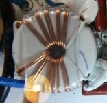
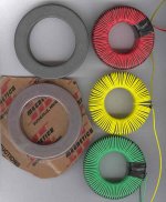
Don, you just opened a new angle for me, thank you. I've been looking into HF switching for DHT filament supply, Berning's ZOTL and HV supply for car . I also read about George's problem on MOSFET bridges due to dead time control which led me to look into TL494 which has a push pull output with dead time control when needed but only usable perhaps up to about 150kHz."This would be a very simple PC board to design for everyone. ...
Something like the attached pictures?Some switchmode techniques for that (like bifilar LV/HV sub sections, ...
I think this simple inverter with no regulation idea can serve the requirements of both the circlotron DC converter and DHT filament supply. With simple adaptation can also be used on a SE setup. Other comments or suggestion?
Attachments

Sure, the same approach could be used for both.
One area of conflict: The audio version requires close attention to minimizing leakage L. The DHT filament source likely wants some means of current limited turn-on. Maybe the conduction pulse widths could be slowly ramped up to 50% at turn on. That might even be helpful to avoid a speaker transient. But the filament version probably wants some significant leakage L for turn-on purposes. Maybe can provide a board position for an optional inductor.
The Mosfets will want some snubber networks to protect them from back EMF. A chip controller can provide the dead time control. If the chip has low side and high side drivers for 2 stacked Mosfet pairs, that would be best. Then only a single primary side winding needed with better control of EMF losses (versus CT'd double primary). That would be quite helpful if one uses multiple ferrite xfmrs to partition the secondary sub-sections. Easier to get close primary to secondary coupling with a single winding primary, rather than a center tapped double primary. Just one set of Mosfets and drivers used for multiple xfmrs. anyway.
A large bore ferrite toroid could provide room for a single layer primary and (up to two) secondary sub-sections (above and below primary, each 1:1 wound, so minimizing leakage L). Enough insulation between layers to minimize common mode capacitance for the audio signal (effectively for the secondary sub-sections to each other, thru the primary coupling capacitances.) The PC board will want some room for multiple xfmrs that way. 10:1 being typical for an OT, that would take 5 2X xfmrs. Maybe could stack the toroids above each other on the PC board with an insulator layer between them. Or put a toroid on front and back PC board side at the same place. I suppose the secondary layers could be wound 2:1 or so (remaining single layer for good coupling), that would significantly reduce the # of toroids. That does however cause capacitance effects between primary and secondary at the carrier frequency versus just audio frequency for 1:1.
The bridge rectifiers for the secondary sub-sections need to be fast and low junction V drop, since there will be a bunch of them effectively in series from secondary partitioning. Some small HF filters on input and output "DC" ports for removing switching glitches.
Some safety approved power source like a wall-wart to power the chip/drivers. Although a CMOS like chip might be able to steal its minute power requirement from the LV "DC" input side. The gate drivers probably draw too much current, to handle 100 to 200 KHz switching that way. Unless some sneaky way to harvest back EMF can be used to charge the local supply cap.
Last edited:
Thanks for your comments, I'll have to dig deep on this one, start real simple and blow some Mosfets up. I prefer modular approach to simplify. Will start a new thread when I have something.
I found this :
DC DC Transformer 8V 32V 12V 24V to ±45V 390V 110V 220V ZVS Capacitor Charging | eBay
it's a step up unit from 12V to (adjustable ) 45 - 390V 200mA
Cost $9.99 free shipping.
Seems that there is a market. I have ordered samples for evaluation.
DC DC Transformer 8V 32V 12V 24V to ±45V 390V 110V 220V ZVS Capacitor Charging | eBay
it's a step up unit from 12V to (adjustable ) 45 - 390V 200mA
Cost $9.99 free shipping.
Seems that there is a market. I have ordered samples for evaluation.
How about this one.
DC AC Converter 12V to 110V 220V AC 150W Inverter Boost Board Transformer Power | eBay
Looks better to me as it has 150W power capacity. produces a 20khz square wave output which should be easy to filter into a smooth DC around 220V.
Might be ideal for a project I am stuck on.
Shoog
DC AC Converter 12V to 110V 220V AC 150W Inverter Boost Board Transformer Power | eBay
Looks better to me as it has 150W power capacity. produces a 20khz square wave output which should be easy to filter into a smooth DC around 220V.
Might be ideal for a project I am stuck on.
Shoog
It will be interesting to see what that 'ZVS' titled module has on it for control and power switching (it looks like a power FET), although they have probably scrubbed off the device markings. The output probably needs to be symmetrically loaded, which could be a brick-wall. The pcb looks well laid out, and some smd bypass ceramic caps at the diode pads could be added if needed.
Hi!
What would be the best for a Battery Powered Tube Amp?
1. DC-DC booster converter or
2. DC to AC converter + using the amplifier's original PSU with transformer?
The reason is that just not to be connected to the network.....
Greets:
Tyimo
What would be the best for a Battery Powered Tube Amp?
1. DC-DC booster converter or
2. DC to AC converter + using the amplifier's original PSU with transformer?
The reason is that just not to be connected to the network.....
Greets:
Tyimo
Linear power supplies are inherently inefficient so DC to DC will give you the best battery life.Hi!
What would be the best for a Battery Powered Tube Amp?
1. DC-DC booster converter or
2. DC to AC converter + using the amplifier's original PSU with transformer?
The reason is that just not to be connected to the network.....
Greets:
Tyimo
Shoog
I once made a mobile transmitter using a pair of Carter 600 volt Dynamotor's. It worked, but was very heavy, and the EMI created by the brushes in the dynamotors could be heard over the air despite multiple LC filters. Not sure if you could clean that up enough for audio.
My recent project worked, was far cheaper, lighter, and more efficient. I simply bought a "12 volt to 220 volt 200 watt car power inverter" from Amazon for about $15, opened it up and soldered a pair of wires across the only 400 volt capacitor in the thing. It provides about 315 volts with no load, and 290 volts with a 200 mA load. The exact inverter I used doesn't seem to be available, but there are other similar models. I chose mine because it was $12.
My recent project worked, was far cheaper, lighter, and more efficient. I simply bought a "12 volt to 220 volt 200 watt car power inverter" from Amazon for about $15, opened it up and soldered a pair of wires across the only 400 volt capacitor in the thing. It provides about 315 volts with no load, and 290 volts with a 200 mA load. The exact inverter I used doesn't seem to be available, but there are other similar models. I chose mine because it was $12.
Yes, that is why I'm afraid too....It worked, but was very heavy, and the EMI created by the brushes in the dynamotors could be heard over the air despite multiple LC filters. Not sure if you could clean that up enough for audio.
- Status
- Not open for further replies.
- Home
- Amplifiers
- Power Supplies
- DC/DC from 12V to 240V@25mA example