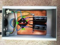
Hi Megajocke - I'll definately add some more insulation to keep it all safe. I'm also going to glue-gun the caps to tha copper slab, the glue offering further insulation.
AndrewT - interested by your comments, but it has to be said that Bryston have used this exact circuit for many years, and offer a 20 year guarantee to boot (I think I read). Surely that means it's tried and tested? (and safe).
If I followed your advice of placing the caps back to back, would I have to re-configure all the wiring? If you coild show me the mods on the Bryston schematic I'd be much obliged.
Thank you,
- john
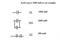
Perhaps the cap's specified by Bryson could withstand a "Worst case" reverse bias indefinitely. To connect back to back would mean doubling the value of each to achieve the same reactance.
parallel to series requires four times as much capacitance. Or allow just one quarter of the current capacity. Remember that you will be operating at half the current compared to a 110/120Vac Bryson.
just remove the two capacitor red wires and connect those two capacitor terminals together.would I have to re-configure all the wiring? If you could show me the mods on the Bryston schematic
"but, can you duplicate Bryson's research and test facilities?"
Of course not - that's why I'm on DIYaudio.com. Asking questions and learning, bit by bit, day by day...
"just remove the two capacitor red wires and connect those two capacitor terminals together."
Aha - OK many thanks for that Andrew. Will report back.
- John
Of course not - that's why I'm on DIYaudio.com. Asking questions and learning, bit by bit, day by day...
"just remove the two capacitor red wires and connect those two capacitor terminals together."
Aha - OK many thanks for that Andrew. Will report back.
- John
Did you find the buzzing worse at various times of day ? I did with mine, and you could see what looked like "data" spikes on the mains itself. Used to start late afternoon.
If you are going to exactly copy the Bryston circuit you need to exactly copy their choice of capacitor, and I don't mean just using the same capacitance value, I mean the exact same specification capacitor (because capacitance is only one of it's parameters).
The diode bridge, as configured by Bryston, gives protection against two diode drops of DC voltage before starting to conduct. That is about 1.4 Volts. Can the capacitors that you have chosen stand 1.4 Volts reverse DC bias?
Personally I am planning on building this type of circuit function at some time in the near future, and I will configure it so that there is only very large capacitor and only one diode drop across that capacitor (i.e. two diodes in total, reverse parallel strapped across the single capacitor). If I measure more that 0.7 Volts DC on the mains at any time I will not change the circuit, but instead be on the 'phone to my electricity supplier.
: )
Mmmm all this seems quite discouraging - think I'll stop using the filter for safety's sake then. Everyone seems to have a different opinion on these things, and since I am something of a layman here I think I'll just put up with the transformer buzz for now...
Thansk for your comments/suggestions guys.
- John
Thansk for your comments/suggestions guys.
- John
Just yank off the caps and run the bridge by itself, it works.
Everybody here will run around yelling, screaming, and pulling their hair at this comment.
Here is a UL approved design from the Crown Studio Reference amplifier, highly praised for its sonics in Stereophile (and other) magazine (s):
http://www.crownaudio.com/pdf/legacy/StudioRefSchematics.pdf
Note 5 says only one bridge is used on the smaller Ref 2 model.
KSTR said:No, not actually the DC. Even with no DC, when there is too high a current through the caps, producing too much voltage drop, the diodes start to conduct. This distorts the waveforms, but symmetrically ==> no DC effect.
If we have DC one of the diodes start to conduct earlier than the other, which result in a part of the DC being effective again (due to the asymmetry).
I just had a brain fart and came up with this.
No reverse bias issues with the big electro, and now only one is needed instead of two.
Cheers,
Glen
Attachments
Hi Glen,
Bit of lateral thinking there. You know there's a "but" coming here 🙂
Won't this introduce harmonic distortion into the primary current flow as you always have two diode volt drops introduced. Much like crossover distortion I suppose.
Very clever thinking though.
Regards Karl
Bit of lateral thinking there. You know there's a "but" coming here 🙂
Won't this introduce harmonic distortion into the primary current flow as you always have two diode volt drops introduced. Much like crossover distortion I suppose.
Very clever thinking though.
Regards Karl
Mooly said:Hi Glen,
Bit of lateral thinking there. You know there's a "but" coming here 🙂
Won't this introduce harmonic distortion into the primary current flow as you always have two diode volt drops introduced. Much like crossover distortion I suppose.
Very clever thinking though.
Regards Karl
EDIT:
DOH!
I really should have run a sim on that circuit before posting it in a super rush inbetween doing other stuff!
I really does not work (with DC current the cap just keeps charging, of course 🙄 )

johnm said:Mmmm all this seems quite discouraging - think I'll stop using the filter for safety's sake then. Everyone seems to have a different opinion on these things, and since I am something of a layman here I think I'll just put up with the transformer buzz for now...
Thansk for your comments/suggestions guys.
- John
Don't be discouraged. As long as it's safe keep learning. Insulate those caps as previously mentioned ( Old "soft" VCR and DVD cases can be good to cut up ) and connect them back to back as Andrew said. Yes you have quartered the value doing that but that might not be so disastrous with 10000 mfd caps. Try it and use it. If it's OK think about making another -- use plastic box and the correct plastic clips for "can style" caps, all easily available.
Buzzing transformers drive me nuts 😉
Attachments
P.S. Whats the correct fuse rating I should be using for this application? I presume it should be a fast blow type as well? Heading to Craplins later so I can pick some fuses up then for this DC trap.
Cheers!
Cheers!
Anti - surge. At least equal to the rating of the internally fitted fuse in the amp. Transformers draw large currents at switch on as the magnetizing field within the core isn't established.
OK in the Dynaco's case it's 1.5 amp, so I'll get a 1.6amp (nearest they do) slow blow from Maplins then.
Thanks 🙂
Thanks 🙂
That should be O.K. The amp I mentioned earlier ( with the 550 va toroid ) would occasionally blow a T6.3 amp fuse at switch on.
- Home
- Amplifiers
- Power Supplies
- DC Blocking Filter for Mains