Found two 2.5k ohm on an old Fosgate board. Changed Q9 & Q7. Replaced Resistors R44 & R36. Powered it up. Resistors and transistors smoked as soon as it was powered up.
Pulled the A92s and resistors off of another board so I could continue to trouble shoot this board. I'll replace them when my order comes in Tuesday. I have 5.6 volts on pad 1 of the driver chips referenced to the -rail. All are equal. No driver chips on the board. How do you check the input signal with -145 volts on the pads referenced to secondary ground? Tried moving the vertical trace on the scope all the way down. Can't see a drive signal.
What scope(s) do you have?
Please (and this applies to anyone who needs repair help) use your sig line to list all equipment you have, editing it as equipment changes. Include the model numbers.
Top of page, menu USER CP >> EDIT SIGNATURE
Oscilloscope (yes or no)
Multimeter(s)
Type of signal source (grounded RCA shields preferred).
Soldering iron
Desoldering pump
Power supply
2 ohm current limiting resistor (hollow cylindrical ceramic 100w preferred)
It's in the repair tutorial if you have it but the following is the setup.
Two probes
Both scope inputs used
Input set to add
Both channels set to DC coupling
Both vertical amps set to the same voltage
Ch2 input set to invert
Bandwidth limited (works best for most measurements in car amps)
Trace aligned to the reference line on the scope's display
Ground leads for both probes connected together
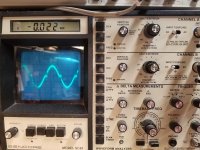
After setting up the scope, you need to confirm that it's working as it should. With the vertical amp set to 5v/div, touching the probe that's connected to Ch1 to the positive terminal of your 12v power supply should make the trace deflect about 2.5 divisions up from the reference (like it always does, seen below). Doing the same with the probe connected to Ch2 should make the trace deflect down about 2.5 divisions. Touching both probes to the positive terminal of the 12v power supply should cause no deflection. If it does, something isn't right.
I know that this may not be as simple as the isolated scope but if you take the time to learn it one time (even if it takes an hour or more of your time), you have that knowledge and this tool to use for the rest of the time you need to use a scope. Using the analog scope will give you much larger and cleaner waveforms.
Two probes
Both scope inputs used
Input set to add
Both channels set to DC coupling
Both vertical amps set to the same voltage
Ch2 input set to invert
Bandwidth limited (works best for most measurements in car amps)
Trace aligned to the reference line on the scope's display
Ground leads for both probes connected together
After setting up the scope, you need to confirm that it's working as it should. With the vertical amp set to 5v/div, touching the probe that's connected to Ch1 to the positive terminal of your 12v power supply should make the trace deflect about 2.5 divisions up from the reference (like it always does, seen below). Doing the same with the probe connected to Ch2 should make the trace deflect down about 2.5 divisions. Touching both probes to the positive terminal of the 12v power supply should cause no deflection. If it does, something isn't right.
I know that this may not be as simple as the isolated scope but if you take the time to learn it one time (even if it takes an hour or more of your time), you have that knowledge and this tool to use for the rest of the time you need to use a scope. Using the analog scope will give you much larger and cleaner waveforms.
Hi Perry, Finally got my new scope probes. Working through setting it up in differential mode. In your instructions you said, "Touching both probes to the positive terminal of the 12v power supply should cause no deflection. If it does, something isn't right." I followed your instructions very carefully. The only difference is I inverted channel A on the SC61. Only because it is the channel that allow me to invert. I don't think it matters as long as one is inverted. Tested it per the instructions. When I touch both probes to the positive of my power supply at the same time I get deflection both directions. Have I made a mistake in setting it up?
Okay. Figured it out. On the SC61 you have to press in both A & B channel buttons. Just pressing A&B will not work. It is working now. I assume I touch one probe to the -rail and the other to the low drive signal to see the difference between the two?
Yes. Now, there is no reason to switch back to the normal setup unless you have to view 2 waveforms. You can use the scope as you would normally, using the chA probe.
To measure deferentially, you will use both probes, just as you would with a multimeter or a battery powered scope.
Use it for instances where you wouldn't normally use it to get accustomed to the way the scope displays the signals/voltage.
To measure deferentially, you will use both probes, just as you would with a multimeter or a battery powered scope.
Use it for instances where you wouldn't normally use it to get accustomed to the way the scope displays the signals/voltage.
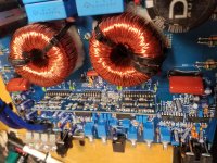
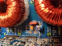
Trying to get this amp to run. Wired a low voltage supply to the rails. +/- 22 volts. Repaired the driver board. Had good signal into the board and good drive out. Put two outputs into one bank. The amp pulled current, the lamp glowed bright, when the relay turned on I got a squeal. Turned the amp off. Pulled the outputs. Installed two more in a different bank. Same thing. Pulled those and tested drive signal to the outputs. Drive on two of the banks. Nothing on the other two. Tested input signal to the board. I have a good input signal when lifted from the driver board. The other pic is the pin soldered to the driver board. Should I pull the board and rebuild yet again?
Attachments

Was the input to the board on the driver board side of the resistor feeding the signal to the driver board?
When everything is working, the signal on the driver board input pin will be cancelled out by feedback from the amplifier.
Does this amp use a jfet or a bipolar transistor for muting?
Was it you that had to install a larger cap across the time delay cap when running on low voltage?
When everything is working, the signal on the driver board input pin will be cancelled out by feedback from the amplifier.
Does this amp use a jfet or a bipolar transistor for muting?
Was it you that had to install a larger cap across the time delay cap when running on low voltage?
"Was the input to the board on the driver board side of the resistor feeding the signal to the driver board?"
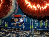
Sorry, I don't understand the question. Here's a pic of the board. I think R201 might be the resistor you mean.
Looks like Q52 might be the mute transistor. KTD1302 bipolar transistor.
I installed a 100uf cap replacing the 47uf.
I repaired the driver board again. Two driver chips were shorted. I replaced the TL072 and LM211 chips also. Checked the drive signals. Looked good. Installed two outputs in one amp bank. Pulls current when I power it up. When the relay engages I get a high pitch squeal in the output. Powered it down and removed outputs. Checked the low side drive. Still good.
(Pics were before I replaced the cap.)
Attachments
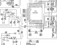
In the diagram below, you will see normal preamp audio that drives the driver board on the op-amp side (A) of the resistor (R187) that drives signal into the driver board.
You will see the output of the amplifier on the 'C' side of R201 (the feedback resistor).
At points labeled 'B', you will see audio only when there is a problem (driver board disabled, output FETs out of the circuit...).
When the amplifier is functioning, the driver board and output will act just like an op-amp. An op-amp does everything that it possibly can to make it's inverting input (the speaker output and the preamp level input combined, here) match its non-inverting input. For this circuit, the ' non-inverting input is the non-inverting input of the TL072 (which is grounded).
This means that when the circuit is working properly, the circuit will work to make the input to the driver board (which is the inverting input to the TL072) match the non-inverting (ground, no signal) input to the TL072. This means that it will work to cancel all signal (make it look like ground) to the input to the driver board (B).
I think the amp that you had to add the cap to was using a jfet for muting. Q52 isn't a jfet here so the muting circuit isn't likely causing a problem unless Q52 is defective. Have you checked it carefully (leakage, opens/shorts)?
What shorted the driver ICs? I missed it if you said that the outputs failed again.
Remove the speaker/load and only monitor the output of the amp with the scope. Does it produce audio or do you only see the signal that was causing the squeal?
Attachments
- Home
- General Interest
- Car Audio
- DC Audio 9.0K